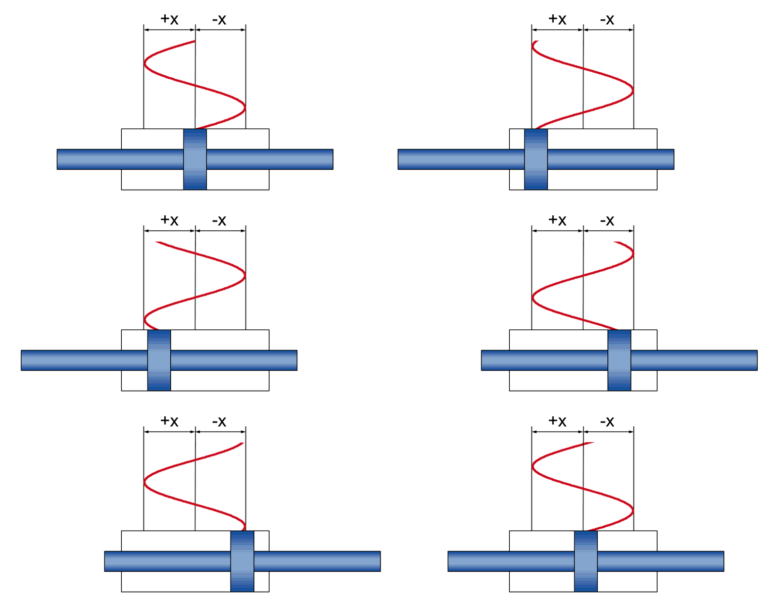
Sinusoidal movement
Calculation of Hydraulic cylinder, Oscillating cylinder
The simplest harmonic sine vibration of a controlled cylinder axis is the cyclic extension and retraction of the piston rod. But completely irregular travel profiles can be mathematically described as well by taking a sine movement as a basis at every point.
The simplified calculation integrated in the HäKo product configurator (Test actuator >> Hydraulic calculation) is intended to design the dynamic movement in a sinusoidal operation. This mainly takes cylinder data into account; other system-relevant components such as hoses or valves and their leakages are not considered.
The sinusoidal motion is defined by the input of amplitude and frequency. Thus, the calculation determines the respective maximum values of the movement, which, however, in the case of a sinusoidal oscillation do not occur simultaneously. For example, the velocity has its maximum value at the moment when the acceleration value is zero.
To determine the cylinder size, this is sufficient for a typical design.
This calculation does not replace the simulation of the complete hydraulic system, which is required in special cases, for example when the system reaches its design limits.
The calculation is used to calculate a movement in sinusoidal operation. It does not cover the behavior when the hydraulic system is switched on or off.
Calculation of forces
The cylinder force Fb at working pressure is the force that is reached in dynamic operation. The working pressure is the actual pressure pb in the cylinder chamber that is reached behind the control valve.
Fb = pb • A
with the effective piston area calculated using bore D2K and piston rod diameter d2s
A = π / 4 • (D2K - d2s)
The cylinder force Fs at system pressure is the force that is reached in static operation. The system pressure is the pressure ps in front of the control valve that is provided by the unit.
Fs = ps • A
Dynamic sine movement
With a sine movement during dynamic operation, physical correlations will occur between
- amplitude +/- x - the actual stroke motion during the vibration
- speed v - the current piston speed (changing constantly over the course of the vibration)
- acceleration a - the current piston acceleration (changing constantly over the course of the vibration)
- frequency f - the sequence of the stroke motion, indicated as the number of vibrations per time unit

| Maximum value |
| v = 2 π f x |
| a = 4 π2 f2 x |
This results in the max. flow rate Q required for the movement
Q = v • A
with the effective piston area A
A = π / 4 • (D2Kolben - d2Stange)
and the accelerating force Fa to be generated by the cylinder
Fa = m • a
On the basis of the maximum acceleration thus calculated and the moving mass, an accelerating force can be calculated which the cylinder has to generate. The piston rod's own mass is allowed for in the calculation program; additional moving masses must be indicated in the respective field.
Servo valve recommendation
The system pressure ps is calculated as follows, taking into account the pressure drop Δp in the control valve:
pb = ps - Δp
With control valves, the pressure drop of the control valve is usually indicated as 70 bar or 10 bar at the nominal flow rate. During operation, however, it will depend on the actual flow rate.
The program will suggest a nominal flow rate for a possible control valve based on the required flow rate. The pressure drop for this case is calculated as well. This provides a quick overview of the required valve size class.
Now the oil leakage flows of the sealing system and the servo valve must be added to the calculated flow rate value.
This design does not render an exact valve determination and design unnecessary.
Further calculation formulas for the design of hydraulic cylinders:
Calculation formulas for hydraulic cylinder design
Calculation of permissible oil velocities
Calculation of the buckling loads of hydraulic cylinders
Buckling cases calculation - piston rod and cylinder attachments