Clamping device for sensitive applicationsRod locking unit with sealing system pressure piston seal
For very sensitive applications, we recommend the design with pressure piston seal, where no pressurized seal is touching the rod. Thus, the sliding friction is very low and remains constant regardless of the releasing pressure.
The hydraulic rod clamp with pressure piston seal is designed for inspection/testing applications and other highly dynamic areas of application, and also for high-precision tasks. This applies especially to combinations with cylinders with non-contacting sealing elements.
- for particularly sensitive applications
- low sliding friction
- speeds of up to 2 m/s possible
- pressure-independent sliding friction
Functional principle of hydraulic rod clamps with pressure piston seal
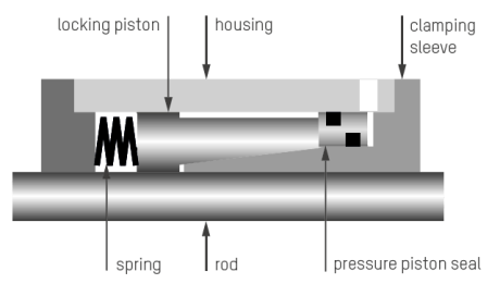
The functional principle of hyddraulic clamping device Ratio-Clamp® is based on the principle of frictional contact: In the pressureless initial position the force stored in the springs is diverted over the cone and clamps down on a round rod. The applied hydraulic releasing pressure moves the locking piston against the spring force to unlock the clamp.
Clamping device Ratio-Clamp® with pressure piston seal
A pressure piston seal that doesn't touch the rod replaces the pressurised sealing elements on clamping sleeve and locking piston. Thus, the very low sliding friction is not influenced by the releasing pressure and will remain constant.

Technical data of locking unit with pressure piston seal
Since clamping geometry and spring are identical to those of the standard Ratio-Clamp®, the same clamping forces can be realised. Due to the smaller hydraulic working area, however, the minimum admissible releasing pressure increases. The max. releasing pressure remains at 160 bar.
- for all round rods with hard surfaces
- load capacity independent of direction
- after 2 million switching cycles the Ratio-Clamp® shall be inspected at the factory
- max. rod speed: 1 m/s with Servocop®, 2 m/s with pressure piston seal
- max. releasing pressure: 160 bar
- working temperatures: -30°C bis +80°C
- fluids: mineral oils, others like water, HFC or Skydrol® on request
| RATIO-CLAMP® |
RATIO-CLAMP® PRESSURE PISTON SEAL |
|||||
| + Releasing pressure + Locking + Sealing system + Certification |
Basic design With spring power Servocop® TÜV |
Basic design With spring power Pressure piston seal TÜV |
||||
| Rod Ø (mm) |
Max. holding load (kN) |
Releasing pressure min. (bar) |
Max. holding load (kN) |
Releasing pressure min. (bar) |
||
| 16 | 10 | 60 | ||||
| 18 | 12,5 | 55 | 12,5 | 75 | ||
| 20 | 14 | 55 | 14 | 75 | ||
| 22 | 17 | 70 | 17 | 90 | ||
| 25 | 20 | 70 | 20 | 90 | ||
| 28 | 31,5 | 90 | 31,5 | 120 | ||
| 30 | 40 | 105 | 40 | 135 | ||
| 32 | 40 | 60 | 40 | 90 | ||
| 36 | 45 | 75 | 45 | 100 | ||
| 40 | 50 | 80 | 50 | 100 | ||
| 45 | 65 | 70 | 65 | 90 | ||
| 50 | 80 | 90 | 80 | 110 | ||
| 56 | 90 | 75 | 90 | 100 | ||
| 60 | 100 | 75 | 100 | 100 | ||
| 63 | 100 | 85 | 100 | 110 | ||
| 70 | 140 | 80 | 140 | 110 | ||
| 80 | 180 | 90 | 180 | 110 | ||
| 90 | 200 | 65 | 200 | 85 | ||
| 100 | 250 | 75 | 250 | 95 | ||
| 110 | 300 | 65 | 300 | 90 | ||
| 120 | 330 | 70 | 330 | 90 | ||
| 125 | 350 | 75 | 350 | 90 | ||
| 140 | 450 | 65 | ||||
| 160 | 750 | 90 | ||||
Other holding forces and rod Ø on request.
Hydraulic locking is possible up to 2,000 kN holding load and 300 mm rod Ø.
The stated values apply to operation with mineral oil. The holding load may differ when using other fluids.

