Control block for your machinery safety
Hydraulic control systems for machines and installations
With regard to the EU Machinery Directive, hydraulic control systems must be designed in such a way that the risk to people and to the environment is as low as possible. This implies that the machine or the drive installed in it must, in addition to its technical function, also meet the safety level specified by the risk analysis.
In hydraulic systems, such control functions are realised with the help of electronic controls in combination with hydraulic blocks. The required valves are compactly housed in control blocks.
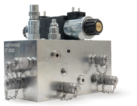
- Switch on, for jolt- and impact-free start-up
- Shut off to isolate drive axes from fluid supply
- Set-up mode, for moving at reduced speed
- Short-circuiting of the chambers, for control-related damping optimisation
General functions
Examples of control blocks
This function disconnects the actuator from the pressure supply. This is achieved with lock valves in the pressure line P.
Setting the sinking speed may be necessary in some cases to protect persons or components. This is realised with a lowering brake valve (back pressure valve) in the return line.
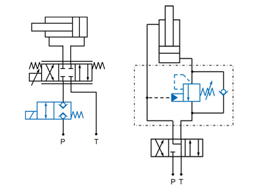
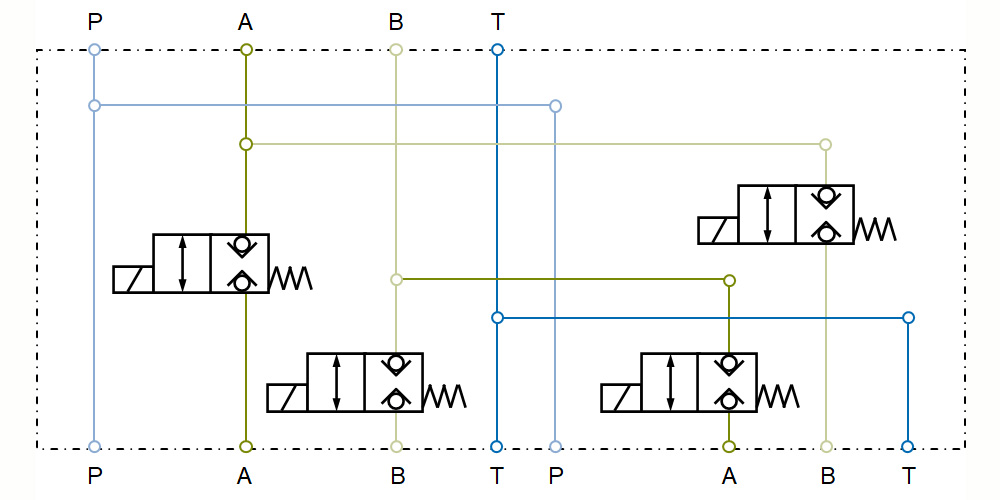
For high dynamics, several servo valves are connected using a mounting block to enable a high flow rate. At low speeds, only one small valve is used. This is realised with two or more control or directional valves.
Each control block is to be individually designed for the respective application. This customising is carried out by the hydraulic block specialists at Hänchen. Below you can find possible functions that may be integrated into the block.
Safety functions
Examples
In addition to the technical function, machines must also meet the safety requirements specified by the risk assessment in order to keep the danger to people low. By means of a redundant design, the following hydraulic functions can be used as safety functions for PLe:
In set-up mode, it may be necessary to reduce the speed to avoid safety-related hazards. This is realised by a bypass with lock valve V2 and throttle V5 and a lock valve V1 in the main flow.
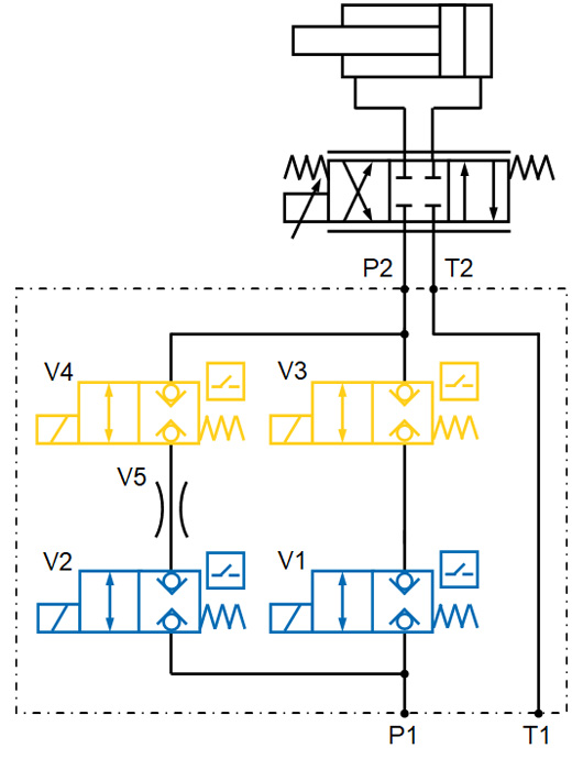
The cylinder position is kept under force by locking the oil in the chambers. This is achieved with the lock valves V1 and/or V2 in lines A and/or B. In the case of throttle gaps inside of the consumer, the functional oil lines must also be shut off.
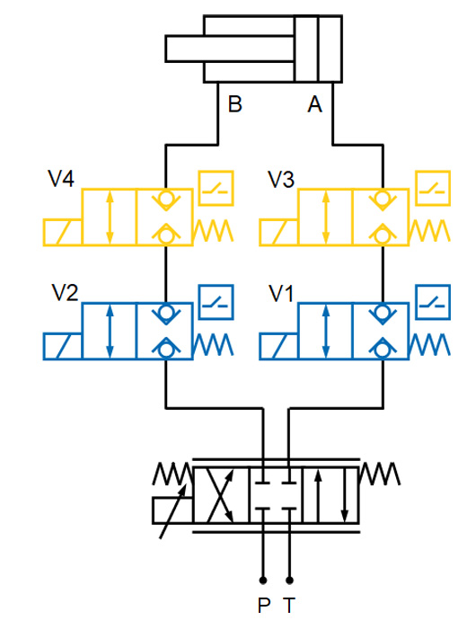
Safety function: Redundant design of the position-monitored lock valves connected in series (V3 und V4)
Application example for a test field
Hydraulic block as safety block
When performing material tests, it must be ensured that persons can work safely in the test field and, for example, cannot suffer any crushing or cutting injuries. The following functions of a hydraulic block are used for the safely control of the hydraulic flow for PLd:
- Regular operation (at 200 l/min) lockable redundantly
- Set-up circuit with reduced speed (at 15 l/min)
- Locking of the set-up circuit in redundant design
- Continuous pressure increase and reduction for almost bumpless connection and disconnection of the consumer
