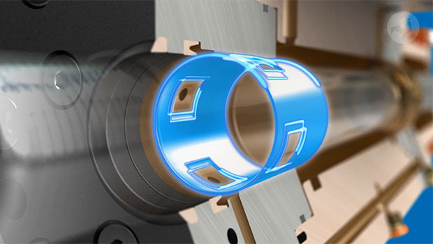
Hydraulic test actuator
Hydraulic actuators for test applications and test systems
The testing sector is versatile and demanding. The selection of the right components for hydraulic test stand are decisive for the optimal operation for a testing machine.
For example, hydraulic test actuators can be used for checking the functional safety of systems, component parts or products, for structural testing of airplanes, refrigeration compressors, automobile exhaust systems, or for simulating loads and movement, such as operational profiles and flight profiles.
Hänchen has one of the largest test hydraulic actuator ranges on the market and also manufactures other components for test stand construction in a wide variety of industries.
Read more about high quality hydraulic cylinders by Hänchen.
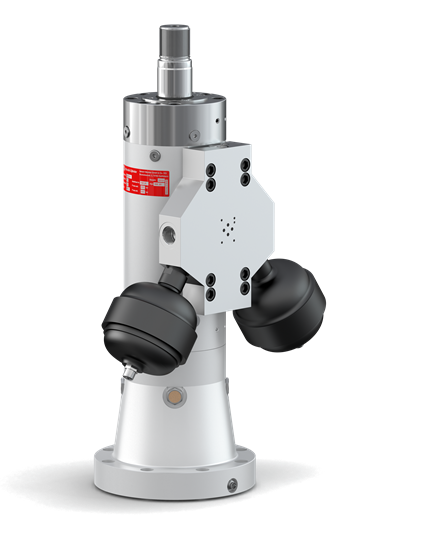
- short changeover times
- adjustable working areas for cost reduction
- compact hydraulic actuator construction
- efficient for varying test series
- high stability and rigidity
- high speeds and high lateral forces
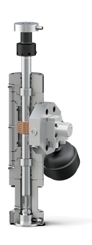
Hydraulic test actuators series 320
Test hydraulic actuators with special features
- For every frequency range and for high lateral forces
The test actuators convince with their stability and high inherent stiffness. They are suitable for high speeds and can reliably bear high lateral forces.
- Modular system for efficient change of applications
Mounting parts und accessories such as spherical rod eyes, integrated position transducers, force transducers, mounting plates, accumulators or control valves fit cylinders with different forces and do not have to be purchased several times for one test field.
- Operation without leak oil pump
Thanks to the elaborate sealing and guiding system, Hänchen cylinders don't need leak oil pumps.
Hänchen's hydraulic actuators of series 320 for test applications are equipped with high-quality bronze coatings for optimum emergency running properties. Unlike other hydraulic test actuator manufacturers and the earlier PL and PLF hydropulse actuators from Schenck.- Protection against unforeseen movement
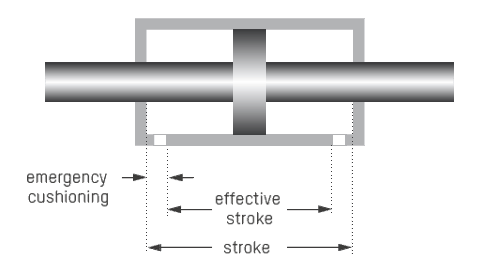
The emergency cushion serves for self-protection of the cylinder and test specimen, and is included in the stroke as standard. The effective stroke is between the two emergency cushioning.
- Bores adjustable to the millimetre
The working areas can be designed individually for the respective requirements. This saves acquisition and operating costs for the required periphery and increases the energy efficiency, e.g. with regard to the system's energy input and cooling power.
Hänchen servo hydraulic actuator series
Test actuators exactly as they should be. Perfect.
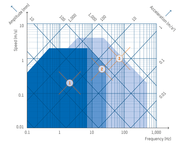
Which cylinder design is the right one for your requirements? The performance map serves for orientation purposes and describes the dynamic movement of a hydraulic drive during a sinusoidal oscillation. The performance classes of the different cylinder designs define the possible applications.
Servo cylinders of the series 120 and 300: slight test actuators for simple testing tasks in typical Hänchen quality – high quality honed surfaces, components with geometrical accuracy, and coordinated sealing elements – these servo cylinders fulfil highest technical requirements for safe and reliably controlled drives.
Use our HÄKO product configurator to help you design and calculate the right hydraulic cylinder or test cylinder.
| Examples for performance map |
|||
Single-rod |
Double-rod |
Double-rod |
|
| Frequency (Hz) | 2 | 20 | 70 |
| Amplitude (mm) | 16 | 4 | 2.3 |
| Speed (m/s) | 0.2 | 0.5 | 1 |
| Acceleration (m/s2) | 3 | 63 | 440 |
Limit values in the performance map without accounting for construction restrictions such as port size, sealing system, guiding system or control valve.
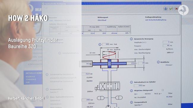
Sinusoidal design in HäKo
You can use our HäKo product configurator to design test actuators as well as round resp. servo actuators (double-rod) using a sinusoidal calculation diagram.
The video explains the sinusoidal movement design tool in detail.
Subtitles in your language:
You can activate the subtitle by pressing the "c" key or in the video at the bottom right. You can have it translated into your language via Settings (cogwheel symbol).
Lateral force design
Lateral forces on the piston rod for 320 series test actuators
The amount of permitted lateral forces is mainly determined by the rod diameter, the guiding system and the cylinder stroke. This results in different values per stroke position. The permitted lateral force in the retracted end position is therefore always greater than in the extended position. For test actuators with longer strokes, the selection of the sealing and guiding systems are of little consequence in regard to resistance to lateral forces.
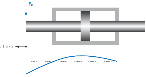
For a quick overview, see the table below Technical data according to the nominal force
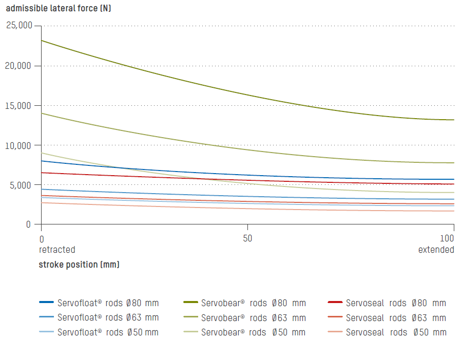
For the exact lateral force curves for every dimension, please use our Hänchen configurator HÄKO at >> Test actuator >> Equipment
Cover design of servo hydraulic test actuators
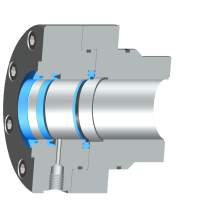
Sealing and guiding system in the cover
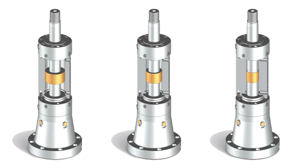
A dynamic test environment requires freemoving, low stick-slip hydraulic cylinders. Hänchen offers three test actuator designs with especially low friction. High production accuracy with very little guide clearance guarantees wear-free use and thus a long service life. You'll find further information on the design of the pistons sealing system here.
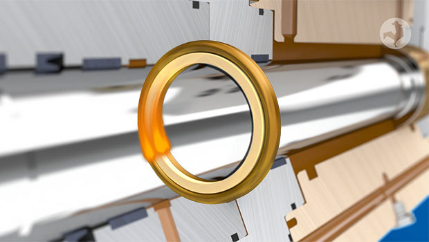
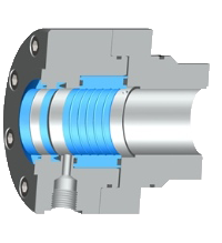
Sealing system Servoseal®
| Guiding system cover | PTFE wear rings = contact guiding element |
| Sealing system of the cover | Servoseal®, lip seal, wiper ring |
| Operating limits | Speed: 3 m/s Temperature: 80 °C Friction: pressure-independent |
Sealing System Servofloat®
| Guiding system cover | PTFE wear rings = contact guiding element |
| Sealing system cover | Floating gap seal, functional oil seal, wiper ring |
| Operating limits |
Speed: 4 m/s |
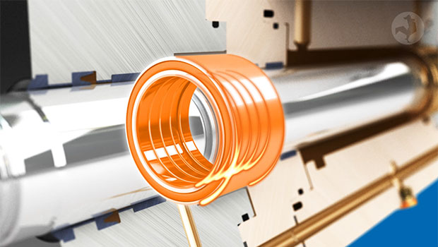
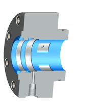
Sealing and guiding system Servobear®
| Guiding system in cover |
Hydrostatic bearing = no-contact guiding elements |
| Sealing system on the cover |
Functional oil seal, wiper ring |
| Operating limits |
Speed: 4 m/s |
Hydraulics design
Flow rate
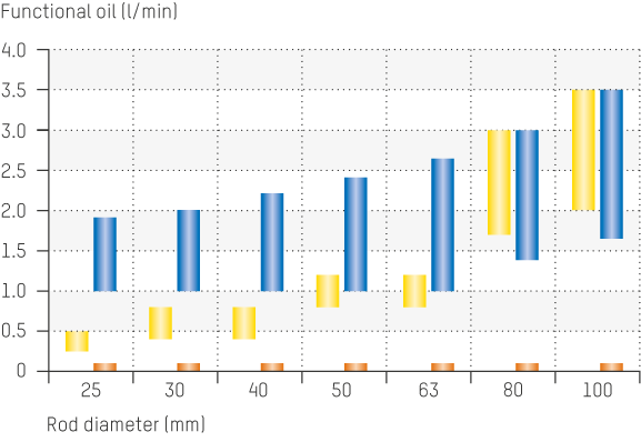
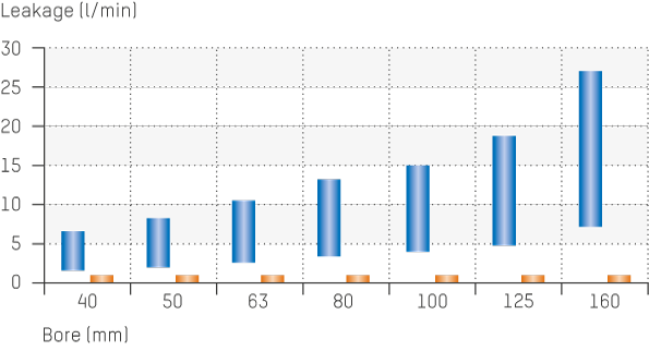
The gap seals used in the test actuator must be observed when designing the necessary flow rate. The penetrating oil flow in the cover is the one required for the Servofloat® and Servobear® design. On the other hand, a leakage occurs at the piston in the "fitted piston" design. This additionally required oil must be added to the flow rate required for the operation of the test cylinder.
Functional oil flow in covers
The Servoseal® sealing system or gap seals are used on the cover or piston for highly friction-sensitive applications with small amplitudes. Servoseal® generates very low leakage, which is hardly measurable during operation. This enables very high hydraulic efficiencies to be achieved.
![]() Servocop®, Servoseal®
Servocop®, Servoseal®![]() Servofloat®
Servofloat®![]() Servobear®
Servobear®
Reference values apply to one cover at 210 bar chamber pressure (working pressure), ISO VG 46 fluid at 55 °C.
Diagram of leakage oil on piston
Gap seals operate with a functional oil flow which is discharged into the tank without pressure via the leak oil port. It must not be sucked off.
![]() Rectangular compact seal, Servoseal®
Rectangular compact seal, Servoseal®
![]() Gap seal
Gap seal
Reference values apply to 210 bar differential pressure at the piston, ISO VG 46 fluid at 55 °C.
Technical data of test actuator
Hydraulic actuators series 320
According to rod diameter
| Rod Ø (mm) |
Type |
Bore (mm) |
Force (kN) 210 bar |
Force (kN) 320 bar |
Stroke (mm) |
| 25 | strong | 28 – 45 | 2,6 – 23,1 | 4,0 – 35,2 | 50 – 170 |
| 30 | strong | 34 – 55 | 4,2 – 35,0 | 6,4 – 53,4 | 50 – 220 |
| 40 | strong | 45 – 70 | 7,0 – 54,4 | 10,7 – 82,9 | 50 – 270 |
| 50 | strong | 56 – 80 | 10,5 – 64,3 | 16,0 – 98,0 | 50 – 450 |
| 63 | strong | 70 – 110 | 15,4 – 134 | 23,4 – 204 | 50 – 450 |
| 80 | slim | 90 – 120 | 28,0 – 132 | 42,7 – 201 | 50 – 450 |
| 80 | strong | 90 – 150 | 28,0 – 266 | 42,7 – 405 | 50 – 450 |
| 100 | slim | 110 – 150 | 34,6 – 206 | 52,8 – 314 | 50 – 450 |
| 100 | strong | 110 – 175 | 34,6 – 340 | 52,8 – 518 | 50 – 450 |
| 125 | slim | 140 – 175 | 65,6 – 247 | 100 – 377 | 50 – 450 |
| 125 | strong | 140 – 200 | 65,6 – 402 | 100 – 613 | 50 – 450 |
| 160 | slim | 180 – 220 | 112 – 376 | 171 – 573 | 50 – 450 |
| 160 | strong | 200 – 260 | 238 – 693 | 362 – 1.056 | 50 – 450 |
| 200 | slim | 240 – 280 | 290 – 633 | 442 – 965 | 50 – 450 |
| 200 | strong | 250 – 320 | 371 – 1.029 | 566 – 1.568 | 50 – 350 |
strong: massive construction (e.g. vertical installation)
slim: light construction (e.g. horizontal installation with spherical rod eyes)
According to nominal force
| Nominal force (kN) |
Design |
Rod Ø (mm) |
Bore (mm) |
Force (kN) 210 bar |
Lateral force when extended (kN) |
||||||||||||
| stroke 100** | stroke 250** | |||||||||||||||||
| Servoseal® | Servofloat® | Servobear® | |||||||||||||||
| 4 | light rod normal rod |
25 30 |
30 34 |
4.5 4.2 |
0.31 0.51 |
0.27 0.44 |
0.51 1.0 |
||||||||||
| 6.3 | light rod normal rod |
30 40 |
36 45 |
6.5 7.0 |
0.51 1.6 |
| |
0.57 |
0.44 1.5 |
| |
0.54 |
1.0 2.5 |
| |
0.67 |
||||
| 10 | light rod normal rod* |
30 40 |
39 47 |
10.2 10.0 |
0.51 1.6 |
| |
0.57 |
0.44 1.5 |
| |
0.54 |
1.0 2.5 |
| |
0.67 |
||||
| 16 | light rod normal rod* reinforced rod |
30 40 50 |
44 51 59 |
17.1 16.5 16.2 |
0.51 1.6 2.8 |
| | |
0.57 1.6 |
0.44 1.5 2.4 |
| | |
0.54 1.2 |
1.0 2.5 4.6 |
| | |
0.67 1.2 |
||||
| 25 | light rod* normal rod reinforced rod |
40 50 63 |
56 64 74 |
25.3 26.3 24.9 |
1.6 2.8 3.8 |
| | | |
0.57 1.6 3.2 |
1.5 2.4 3.6 |
| | | |
0.54 1.2 2.9 |
2.5 4.6 7.8 |
| | | |
0.67 1.2 2.3 |
||||
| 40 | light rod normal rod* reinforced rod |
40 50 63 |
64 70 80 |
41.2 39.6 40.1 |
1.6 2.8 3.8 |
| | | |
0.57 1.6 3.2 |
1.5 2.4 3.6 |
| | | |
0.54 1.2 2.9 |
2.5 4.6 7.8 |
| | | |
0.67 1.2 2.3 |
||||
| 63 | light rod* normal rod reinforced rod |
50 63 80 |
80 88 101 |
64.3 62.3 62.7 |
2.8 3.8 6.7 |
| | | |
1.6 3.2 4.5 |
2.4 3.6 6.4 |
| | | |
1.2 2.9 5.1 |
4.6 7.8 13.3 |
| | | |
1.2 2.3 4.4 |
||||
| 100 | light rod normal rod* reinforced rod |
63 80 100 |
100 112 127 |
99.5 101.3 101.1 |
3.8 6.7 11.1 |
| | | |
3.2 4.5 9.7 |
3.6 6.4 10.3 |
| | | |
2.9 5.1 8.7 |
7.8 13.3 24.9 |
| | | |
2.3 4.4 9.7 |
||||
| 160 | light rod* normal rod reinforced rod |
80 100 125 |
127 140 160 |
160.5 158.3 164.5 |
6.7 11.0 16.2 |
| | | |
4.5 9.7 15.9 |
6.4 10.3 15.1 |
| | | |
5.1 8.7 14.6 |
13.3 24.9 49.5 |
| | | |
4.4 9.7 23.9 |
||||
| 250 | light rod normal rod* reinforced rod |
100 125 160 |
160 175 202 |
257.3 247.4 250.8 |
11.0 16.2 24.7 |
| | | |
9.7 15.9 24.0 |
10.3 15.1 22.1 |
| | | |
8.7 14.9 22.7 |
24.9 49.5 81.6 |
| | | |
9.7 23.9 42.2 |
||||
| 400 | light rod* normal rod reinforced rod |
125 160 200 |
200 225 225 |
402.0 412.7 412.7 |
16.2 24.7 31.7 |
| | | |
15.9 24.0 30.6 |
15.1 22.1 |
| | | |
14.6 22.7 |
49.5 81.6 99.1 |
| | | |
23.9 42.2 58.4 |
||||
| 630 | normal rod* reinforced rod |
160 200 |
225 280 |
650.3 633.3 |
24.7 31.7 |
| | |
24.0 30.6 |
22.1 | | | |
22.7 | 81.6 99.1 |
| | |
42.4 58.4 |
||||
| 1.000 | normal rod* | 200 | 320 | 1,029.2 | 31.7 | | | 30.6 | | | 99.1 | | | 58.4 | ||||||
The assignment of the piston to the nominal force serves for orientation purposes. For optimised design under consideration of hydraulics, dynamics or weight, please use the calculation in our product configurator HÄKO.
* Reference to common standard dimensions such as the Schenck actuators.
** The mechanical guiding systems of Servoseal® and Servofloat® are limited by the permissible surface pressure, but can absorb very high lateral forces and deflections during long strokes. Hydrostatic bearings (Servobear®) are characterised by a very high bearing and lateral load capacity, especially with short strokes.
