Hydraulic clamping device Ratio-Clamp®Hydraulic rod locking unit from Hänchen
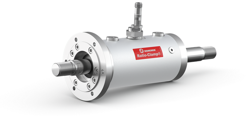
The patented hydraulic clamping unit Ratio-Clamp® serves to protect human, machine and tools in case of a power failure or system shutdown. This rod clamping device fixes axes during the process or for highly dynamic applications and test processes.
Application areas of hydraulic rod locking:
- Fixation of all types of round rods in any position
- Out of standstil, for braking in the occasional case of an emergency, even while moving
- Clamping force without energy supply for unlimited time
- An additional safety component for gravity loaded axes
- Clamping and releasing without axial rod movement
- clamping effect in case of a power failure
- allowance- and wear-free locking
- load capacity independent of direction
- clamps all round rods
- TÜV-certified
Application areas of hydraulic rod lock
There are many situations where rods have to be held in a certain position: For example to protect people, machines and tools in case of power failures or plant shutoffs. Or to fix axes during a manufacturing process. And also for all highly dynamic applications and test processes.
Here are some examples from practical experience:
- Grinding machine > production
During the production process of ICE rail sleepers, extremely large and heavy concrete workpieces must be positioned for grinding safely and with an accuracy of 0.01 mm. Hänchen's hydraulic cylinders and Ratio-Clamp® clamping units are designed exactly for these requirements.
- Aviation > testing technology
The setups for aviation tests have been refined to the last detail. Hänchen cylinders are used in different fields of testing, simulating ambient conditions and loads during different flight phases. Ratio-Clamp® clamping units are used to protect the intricately constructed and expensive systems.
- Press > production
Hänchen lock cylinders guarantee safe movements of the press. Clamping units ensure safety during the pressing process in moulding and injection presses for the production of synthetic and rubber moulded parts in accordance with EN 289.
- Railway technology > maintenance
For maintenance purposes, trains must be fixed in the raised state – the Ratio-Clamp® is ideally suited for this purpose. The clamping units hold the train securely in position until the work has been completed and it can return to the rails.
- Profiling machine > production
Hänchen clamping units ensure precise machining and consistent quality in the production of metal profiles. During the production process, they facilitate the machining of the profiles by locking the forming tools in place. Ecological and efficient, purely with spring power.
The functional principle in detail
Hänchen's Ratio-Clamp® offers safety while saving energy costs. Thanks to its sophisticated functional principle, the hydraulic clamping device features some fundamental advantages when compared with other locking systems.
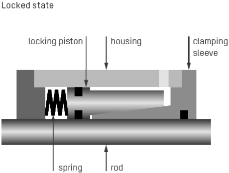
Ratio-Clamp® rod locks works mechanically by using frictional contact: The power is directed through springs to a clamping sleeve which holds the rod radially using friction. The load capacity of the fixation is not influenced by the direction. The hydraulic releasing pressure moves the locking piston against the spring power to unlock the clamp - the rod can be moved in both directions. When the hydraulic pressure drops, the power stored in the springs is released, and the rod is locked.
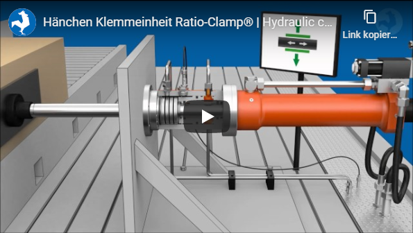
Video to functional principle of the clamping device Ratio-Clamp® on the example of a gantry milling machine.
- Locking and securing loads
If the releasing pressure drops, the force stored in the springs is released and causes the rod to clamp. Thus the load is secured and the Ratio-Clamp® is ready to take over the load.
- Loading
Loading is possible immediately after clamping. No axial movement of the rod is required. In the clamped state, the forces in both directions can be kept free of play.
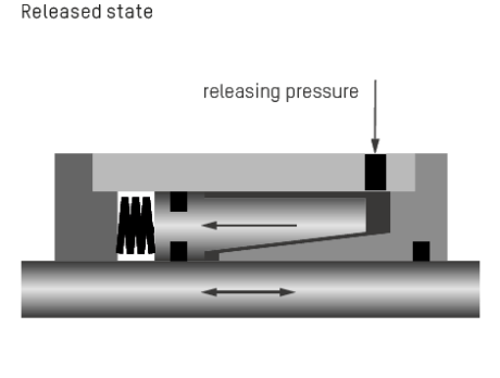
- Releasing
The locking piston moves against the spring power by hydraulically releasing pressure and releases the clamping force. The rod can be moved in both directions.
- Overloading
Short-term overloading with slipping of the rod is possible without damaging the rod or the clamping unit.
Energy efficiency and precision for every case
Do you have an application where a round rod has to be held in a specific position? There are different ways to achieve this: by electronic control, shutting off all ports, locking with pivot pins or by using the clamping unit Ratio-Clamp®. The Ratio-Clamp® scores with numerous advantages.
- Stepless clamping without energy supply
- Fixes precisely at the desired positions
- Holds position at temperature fluctuations
- Savings in energy costs through clamping with spring power
Comparison of advantages and disadvantages of locking options for round rods
| Electronic control |
Port lock-off |
Pivot pin locking |
Clamping unit Ratio-Clamp® |
|
| Energy efficiency | – | + | + | + |
| Position accuracy | + | – | + | + |
| Independence from external influences |
+ | – | + | + |
| Effort | – | + | – | + |
| Flexible positioning | + | + | – | + |
Regardless of hydraulics and electronics, Ratio-Clamp® will hold the piston rod in any position for any amount of time – no energy supply required.
Case example: The energy required for clamping a piston rod:
A hydraulic cylinder with an 80 mm bore is moved at 150 bar with a speed of 0.5 m/s. The drive power required is 38 kW.
Power loss when holding
When using an electronic control system with a controlled pump, the power loss to be expected at the pump is approx. 1.25 kW, plus a loss of approx. 1.25 kW at the control valve. So in this example, the total power loss with the controlled drive would be 2.5 kW. With a holding time of 5.000 hours a year, you'd lose 12.000 kWh.
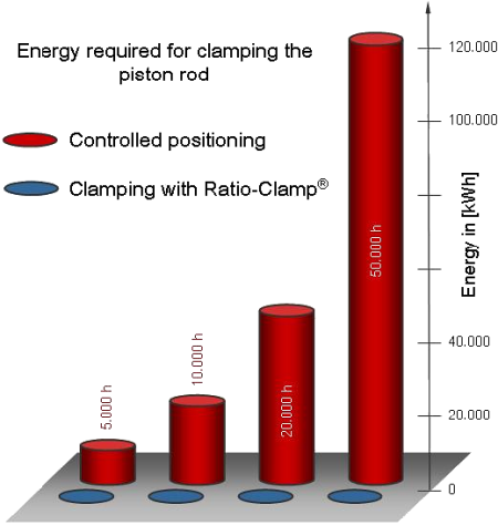
Ratio-Clamp® uses spring power for holding, which is why there is no need for hydraulic or electric power.
EquipmentCharacteristics of hydraulic clamping devices
- Releasing pressure
Basic design
The basic releasing pressure required for releasing the clamping unit is between the minimum pressure and the maximum admissible pressure of 160 bar.
Reduced design
For application cases with low supply pressure, a version designed with a reduced released pressure is available.- Certification
TÜV certification
Every Ratio-Clamp® is type tested by TÜV SÜD.
DGUV Test
The clamping unit is also available with a DGUV Test certification (testing and certification system of the "Deutsche Gesetzliche Unfallversicherung"). Ratio-Clamp® has a B10D value according to EN ISO 13849-1 for use as a redundant safety component. The double safety requirement by the DGUV for the maximum holding load is already taken into account in the load specification.
learn more
- Locking
Locking with spring power
Usually, energy stored in springs is used to clamp a rod. This means that the rod can be held for unlimited periods of time without any energy supply.
Hydraulic locking
When very high holding loads are required, the clamping unit can also be locked hydraulically. For the release, hydraulic pressure is used as usual.- Sealing system
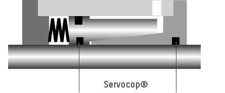
Servocop®: compact seal, lip seal, wiper ring
The basic type of Ratio-Clamp® uses the frictionoptimised sealing system Servocop®. Here, the primary seal touches the rod. The maximum speed of the rod is 1 m/s.
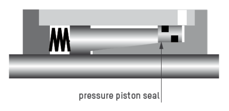
Pressure piston seal, lip seal, wiper ring
For very sensitive applications, we recommend the design with pressure piston seal, where no pressurised seal touches the rod. Thus, the sliding friction is very low and remains constant regardless of the releasing pressure. The maximum speed of the rod is 2 m/s.
learn more
Accessories for the clamping device Ratio-Clamp®
Quality taken to the next level.
- Hydraulic cylinders
-
Ratio-Clamp® can be combined with Hänchen hydraulic and standard cylinders and with all cylinders from other manufacturers.
A fixed flange is used for attachment to Hänchen hydraulic cylinders or cylinders pursuant to ISO 6020-1, ISO 6020-2 and other makes. For this purpose, the rod must be extended according to the length of the clamping unit. If attached separately, the clamping unit can also be loosely installed using a collar flange to compensate for axis misalignment.

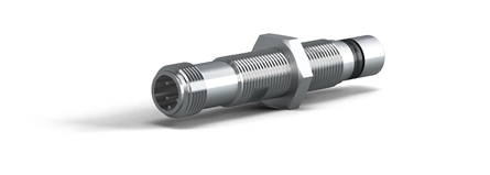
- Proximity switch
-
The respective state – rod locked or released – can be monitored via inductive proximity switches. The device for mounting a proximity switch is available as standard. On request, the clamping unit can be equipped with two proximity switches. When using the Ratio-Clamp® as a safety component or with required DGUV Test certification, it is obligatory to have a proximity switch with diagnostic output installed. This also monitors the function of the switch and supply line.
- Control block
-
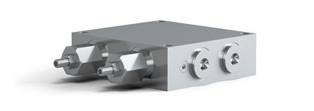
Used when Ratio-Clamp® is installed on a hydraulic cylinder. It provides correct and consistent control and thus reduces the complexity of the required wiring.
When controlling a Ratio-Clamp®, it must first be released by applying pressure to the releasing port – only then may the rod be moved. When using a clamping unit together with a hydraulic cylinder, it can be done by means of a hydraulic sequential control or by electronic monitoring. For example, in order to build up counterpressure, sensors in an electronic control system can measure the load on vertically installed cylinders. This prevents the rod from jolting when releasing.
This can also be achieved with a hydraulic control block: first the releasing pressure is built up, then the cylinder is pressurised. Matching valves locks the pressure in the cylinder so that the Ratio-Clamp® can be unlocked almost without jolts even when handling vertical loads.
- Rod requirements
-
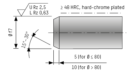
The round rod to be clamped shall have a hard surface and must meet the minimum requirements when installing the Ratio-Clamp®. A honed rod is recommended.
Technical data of hydraulic clamping device
- for all round rods with hard surfaces
- load capacity independent of direction
- after 2 million switching cycles the Ratio-Clamp® shall be inspected at the factory
- max. rod speed: 1 m/s for Servocop®, 2 m/s for pressure piston seal
- max. releasing pressure: 160 bar
- working temperatures: -30°C bis +80°C
- fluids: mineral oils, others like water, HFC or Skydrol® on request
| RATIO-CLAMP® |
RATIO-CLAMP® REDUCED RELEASING PRESSURE |
|||||
| + Releasing pressure + Locking + Sealing system + Certification |
Basic design With spring power Servocop® TÜV |
Reduced design With spring power Servocop® TÜV |
||||
| Rod Ø (mm) |
Max. holding load (kN) |
Releasing pressure min. (bar) |
Max. holding load (kN) |
Releasing pressure min. (bar) |
||
| 16 | 10 | 60 | 8 | 50 | ||
| 18 | 12,5 | 55 | 8 | 35 | ||
| 20 | 14 | 55 | 9 | 40 | ||
| 22 | 17 | 70 | 12 | 45 | ||
| 25 | 20 | 70 | 15 | 50 | ||
| 28 | 31,5 | 90 | 25 | 65 | ||
| 30 | 40 | 105 | 30 | 75 | ||
| 32 | 40 | 60 | 30 | 45 | ||
| 36 | 45 | 75 | 32 | 50 | ||
| 40 | 50 | 80 | 38 | 55 | ||
| 45 | 65 | 70 | 45 | 50 | ||
| 50 | 80 | 90 | 55 | 60 | ||
| 56 | 90 | 75 | 60 | 50 | ||
| 60 | 100 | 75 | 70 | 55 | ||
| 63 | 100 | 85 | 60 | 55 | ||
| 70 | 140 | 80 | 100 | 55 | ||
| 80 | 180 | 90 | 130 | 65 | ||
| 90 | 200 | 65 | ||||
| 100 | 250 | 75 | ||||
| 110 | 300 | 65 | ||||
| 120 | 330 | 70 | ||||
| 125 | 350 | 75 | ||||
| 140 | 450 | 65 | ||||
| 160 | 750 | 90 | ||||
Other holding forces and rod Ø on request.
Hydraulic locking is possible up to 2,000 kN holding load and 300 mm rod Ø.
The stated values apply to operation with mineral oil. The holding load may differ when using other fluids.

