
Servo hydraulic actuator
Hydraulic servo cylinders with valve and sensor technology
Precisely positioning large forces: Hänchen servo hydraulic actuators with integrated position transducers reliably master this requirement. By using appropriate valves, precise position and force control at high accelerations can be easily achieved.
Our servo hydraulic cylinders are also perfectly suited as lightweight test actuators or for long-stroke testing tasks.
If you require support for your hydraulic system, Hänchen, as a manufacturer of industrial hydraulic cylinders, offers a range of services extending from hydraulic integration into your plant to complete hydraulic special machines.
Servo hydraulic actuator
Hydraulic servo cylinders with valve and sensor technology
Precisely positioning large forces: Hänchen servo hydraulic actuators with integrated position transducers reliably master this requirement. By using appropriate valves, precise position and force control at high accelerations can be easily achieved.
Our servo hydraulic cylinders are also perfectly suited as lightweight test actuators or for long-stroke testing tasks.
If hydraulic cylinders are required for very high frequencies and accelerations, our test actuators for testing systems are the right choice.

- Optimal price-performance ratio
- Suitable for testing tasks with long strokes
- As single-rod or double-rod cylinder
- With integrated position transducer
- Low dead weight
- Optionally with mounting plate for control valve
Sensor technology and valves for servo hydraulic actuators
Perfect for dynamic industrial and testing tasks
For the necessary sensitivity, Hänchen offers suitable sensor technology components and valves – everything for highly dynamic, precise drives with high energy density.


Condition Monitoring
for hydraulic cylinders
For the operation of the hydraulic cylinder in an Industry 4.0 environment, additional sensors can provide data for condition monitoring:
- Pressure transducer in the chambers analyse the friction behavior
- Temperature and color sensors provide information on the condition of the fluid
- Online particle counters indicate the degree of contamination of the system
- Flow sensors on the functional oil channel provide an indication for a seal replacement.
Series of servo hydraulic actuators from Hänchen
For controlled movements
- Servo hydraulic actuator series 120
- bore 40 mm to 180 mm
- working pressure up to 150 bar
- as single-rod cylinder and double-rod cylinder
- cylinder in round-head design
- various mounting types
- honed and chrome-plated piston rod
- test pressure = 1.5 x max. working pressure
- Servo hydraulic actuator series 160
- bore 50 mm to 125 mm
- working pressure up to 160 bar
- as single-rod cylinder
- cylinder in round-head design according to ISO 6020-1
- various mounting types
- honed and chrome-plated piston rod
- test pressure = 1.5 x max. working pressure
- Servo hydraulic actuator series 300
- bore 50 mm to 140 mm
- working pressure up to 300 bar
- as single-rod cylinder and double-rod cylinder
- cylinder in round-head design
- various mounting types
- honed and chrome-plated piston rod
- test pressure = 1.5 x max. working pressure
- Test hydraulic actuator series 320
- bore 28 mm to 320 mm
- working pressure up to 320 bar
- as double-rod cylinder
- honed and chrome-plated piston rod
- test pressure = 1.5 x max. working pressure
Hydraulic actuators are suitable for hydrodynamic applications. You can find out more about this under test actuator.
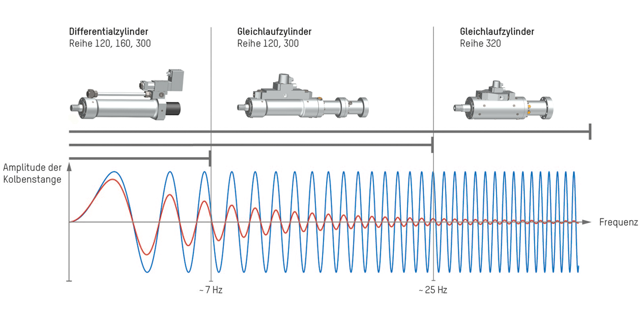
Suitability of the servo cylinder series according to frequency range
The required dynamics of the drive determine the cylinder's type of effect. With fast control valves, even single-rod cylinders achieve a high profile quality at high frequencies.
The limit values shown in the diagram are intended as guidelines for your design. They depend on various operating conditions - we will help you with your selection.
Equipment servo hydraulic actuator
Sealing and guiding systems
The sealing system in the cover and on the piston are the core of a hydraulic cylinder and determine its application possibilities. This defines the friction characteristics and stick-slip behavior of the industrial hydraulic cylinder, the achievable speeds, and how side loads affect it. For servo hydraulic actuators operated in an oscillating manner, we recommend the Servoslide® synthetic guide or PTFE wear rings as the guiding system in the cover.
Servoseal cylinder
The modern method of testing
By using our Servoseal® seals in the slim series 120 and 300, the need for massive test actuators is eliminated in applications with frequencies up to 25 Hz.
Your advantages at a glance:
- Virtually no friction and therefore no wear
- Function without leak oil flow at the cover and leakage across the piston
- No minimum amplitude required
- strokes from 1 mm to over 1,000 mm
Questions about Servoseal cylinders
Cost-effective test actuators for endurance tests
- What is Servoseal® and what makes this seal special?
-
Servoseal® is a dynamic sealing system for pistons and covers, developed by Hänchen itself and tested on its own seal test stand. An integrated carbon retaining ring prevents the seal from being pressed too strongly against the sliding surface by the hydraulic pressure. As a result, Servoseal® combines very low friction with minimal leakage and is also suitable for tests with small movement amplitudes. This enables precise, energy-efficient, and economical test actuators with low flow rate requirements.
- Is there a cost-effective alternative to classic test actuators with low leakage?
-
For many testing tasks, a test actuator with a Servoseal® sealing system is suitable. The Servoseal® significantly reduces leakage across the piston and cover and requires less flow rate compared to gap seals. This often allows for the use of smaller valves and hydraulic components, which lowers investment and operating costs. At the same time, the low friction ensures precise and energy-efficient movement.
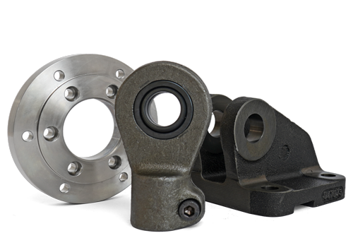
Accessories and tools for servo hydraulic actuators
Mounting elements and system components
You can find our standard accessories and tools in the HÄKO product configurator to match your selected cylinder.

for industrial and test applications
Type of effect: single-rod cylinder, double-rod cylinder | Sealing systems: Basic design, Servocop®, Servoseal®*, Servofloat® |
Speeds: up to 2 m/s | Stroke: 1 - 1,500 mm
| Series 120 | Series 160 | Series 300 | |||||||||
| Bore (mm) |
Rod Ø (mm) |
Force F1 | F2 (kN) |
Max. pressure** (bar) |
Force F1 | F2 (kN) |
Max. pressure** (bar) |
Force F1 | F2 (kN) |
Max. pressure** (bar) |
||||
| 40 | 25 | 18,8 | | 11,5 | 150 | --- | --- | --- | --- | |||
| 50 | 25 28 30 40 |
29.5 | --- 29.5 | |
22.1 --- 18.8 --- |
150 --- 150 --- |
31,4 | |
--- 21.6 --- --- |
--- 160 --- --- |
58.9 | 58.9 | |
--- --- 37.7 21.2 |
--- --- 300 300 |
|
| 60 | 30 40 50 |
42.4 | 42.4 | |
31.8 23.6 --- |
150 150 --- |
--- --- --- |
--- --- --- |
84,8 84,8 |
--- 47.1 25.9 |
--- 300 300 |
||
| 63 | 36 | --- | --- | 49,9 | | 33,6 | 160 | --- | --- | |||
| 80 | 40 45 50 60 |
75.4 | 75.4 | |
56.5 --- 45.9 --- |
150 --- 150 --- |
80,4 | |
--- 55.0 --- --- |
--- 160 --- --- |
150.8 | 150.8 | |
--- --- 91.9 66.0 |
--- --- 300 300 |
|
| 100 | 50 56 60 80 |
117.8 | --- 117.8 | |
88.4 --- 75.4 --- |
150 --- 150 --- |
125,7 | |
--- 86.3 --- --- |
--- 160 --- --- |
235.6 | 235.6 | |
--- --- 150.8 84.8 |
--- --- 300 300 |
|
| 125 | 60 70 80 100 |
184.1 | 184.1 | |
141.7 --- 108.7 --- |
150 --- 150 --- |
196,3 | |
--- 134.8 --- --- |
--- 160 --- --- |
368.2 | 368.2 | |
--- --- 217.4 132.5 |
--- --- 300 300 |
|
| 140 | 80 100 |
230.9 | 230.9 | |
155,5 113,1 |
150 150 |
--- --- |
--- --- |
461,8 | |
--- 226.2 |
--- 300 |
||
| 160 | 80 100 |
301.6 | 301.6 | |
226,2 183,8 |
150 150 |
--- --- |
--- --- |
603,2 | |
--- 367.6 |
--- 300 |
||
| 180 | 100 120 |
381.7 | 381.7 | |
263,9 212,1 |
150 150 |
--- --- |
--- --- |
763,4 | |
--- 424.1 |
--- 300 |
||
| 200 | 100 120 140 |
628.3 | 628.3 | |
471.2 402.1 --- |
200 200 --- |
--- --- --- |
--- --- --- |
942,5 | |
--- --- 480.7 |
--- --- 300 |
||
| 220 | 120 140 160 |
760.3 | 760.3 | |
534.1 452.4 --- |
200 200 --- |
--- --- --- |
--- --- --- |
1.140,0 | |
--- --- 537.2 |
--- --- 300 |
||
| 250 | 120 140 180 |
981.7 | 981.7 | |
755.6 673.9 --- |
200 200 --- |
--- --- --- |
--- --- --- |
1.472,0 | |
--- --- 709.2 |
--- --- 300 |
||
| 300 | 160 200 |
1.413,7 | |
1,011.6 --- |
200 --- |
--- --- |
--- --- |
2.120,6 | |
--- 1,178.2 |
--- 300 |
||
* Not for series 160
** When pivot mounting the pressure is limited to 120 bar.
F1 = force extending when extend the cylinder | F2 = force retracting when retraction the cylinder
For double-rod cylinders, retracting and extend correspond to the value F2.