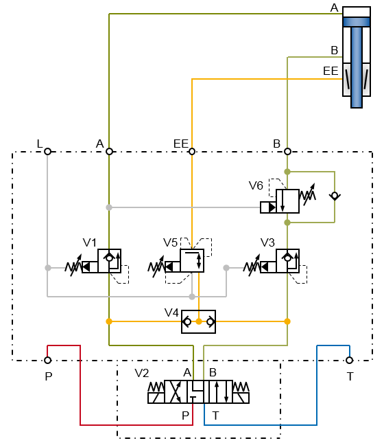
Control block
Controll of the Clamping unit Ratio-Clamp® with a work sequence
When controlling a Ratio-Clamp®, it must first be released by applying pressure to the releasing port – only then may the rod be moved.
When using a clamping unit together with a hydraulic cylinder, it can be done by means of a hydraulic sequential control:
First the releasing pressure is built up, then the cylinder is pressurised. Matching valves locks the pressure in the cylinder so that the Ratio-Clamp® can be unlocked almost without jolts even when handling vertical loads.
Installed between directional control valve V2, clamping unit and hydraulic cylinder, the control block ensures a logical and functionally correct control and thus reduces the circuitry complexity for the user to a minimum.
Control block basic type: suitable for a horizontal mounting position of the clamping unit, use up to 160 bar.
Control block universal type: suitable for a horizontal and vertical mounting position of the clamping unit, use up to 300 bar.
Integrated functions
Follow-up procedure
When using a clamping unit Ratio-Clamp® together with a hydraulic cylinder, the clamping unit must first be released by pressurizing the releasing port EE, only then the rod may be moved by pressurizing the effective surfaces of the cylinder via the connection lines A or B.
If the pressure in the connecting lines A or B to the hydraulic cylinder drops, for example by switching a directional control valve after reaching a certain position, the pressure at the unlocking port EE also drops and the Ratio-Clamp® clamping unit is locked again.
This process works automatically both in the basic type or in the universal type when using the control block. The shuttle valve V4 controls the release pressure of the clamping unit and only when the pressure is high here the respective pressure sequence valves V1 or V3 pressurise the corresponding chambers of the cylinder.
Load holding
When installed vertically, the load on the cylinder is taken over by the clamping unit. The load is secured.
In the cylinder chamber at port B, the holding pressure corresponding to the load is locked by the velocity fuse V6.
When restarting after clamping, that is when unlocking, this holding pressure takes over the load until the opening pressure of the valve is reached and the cylinder moves. This enables an almost jerk-free restart.
This function is implemented only in the universal type.
Pressure reduction
The pressure reducing valve V5 limits the release pressure to 160 bar. This is the maximum permissible unlocking pressure of a Ratio-Clamp® clamping unit.
This function is particularly necessary if the cylinder is to be operated at higher pressure.
Please note that the clamping unit may only be used up to the maximum permissible holding force.
This function is implemented only in the universal type.

| A |
port extending | V1, V3 | pressure sequence valves |
| B | port retracting | V2 | directional control valve |
| EE | unlocking port | V4 | shuttle valve |
| L | leakage port | V5 | pressure reducing valve pmax = 160 bar |
| P, T | port pressure, tank | V6 | velocity fuse |
Even when using the clamping unit without cylinder, it must be noted that the clamping unit must first be completely unlocked before the rod moves.
When used for high performance levels, the velocity fuse V6 can also be designed with feedback.
Technical data
Maximum pressure pmax = 300 bar
Volume flow Vmax = 45 l/min
Oil temperature -20 °C bis 80 °C
Seals made of NBR
Mineral oil VG 20 to 68 HLP, HLPD according to DIN 51524, purity 19/17/14 according to ISO 4406