

Servohydraulic test actuators
Hydraulic test cylinder for testing and validation applications
The testing sector is versatile and demanding. The selection of the right components for hydraulic test stands is decisive for the optimal operation of a test machine.
The hydraulic test cylinders are used, for example, for testing the functional reliability of systems, components, or products, for structural tests of aircraft, refrigeration compressors, exhaust plants of automobiles, or for simulating loads and movements, such as driving profiles and flight sequences.
Hänchen has one of the largest test actuator programs on the market and also acts as a manufacturer of other components for test stand construction in a wide variety of industries. In addition, we offer the implementation of complete, individual test machines.
Servohydraulic test actuators
Hydraulic test cylinder for testing and validation applications
The testing sector is versatile and demanding. The selection of the right components for hydraulic test stands is decisive for the optimal operation of a test machine.
The hydraulic test cylinders are used, for example, for testing the functional reliability of systems, components, or products, for structural tests of aircraft, refrigeration compressors, exhaust plants of automobiles, or for simulating loads and movements, such as driving profiles and flight sequences.
Hänchen has one of the largest hydraulic test actuator programmes on the market and also acts as a manufacturer of other components for test stand construction in a wide variety of industries.
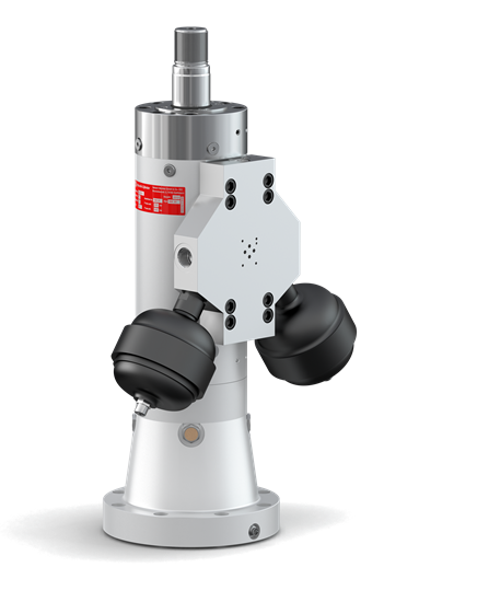
- Operation without leak oil pump
- Adaptable working areas to reduce costs
- Three sealing concepts to choose from
- Efficient for changing test series
- High stability and rigidity
- High speeds and high lateral forces
Hydraulic test cylinders of the 320 series
Test hydraulic actuators with special features
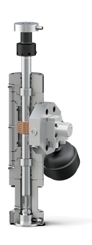
For every frequency range and high lateral forces
The test actuators impress with their stability and high inherent stiffness. They are suitable for high speeds and can reliably absorb high lateral forces.
Modular system for efficient application change
Mounting parts and accessories such as spherical rod eyes, integrated position transducers, force transducers, mounting plates, accumulators or control valves fit on cylinders of different forces and do not have to be procured several times in a test field.
Operation without leak oil pump
Thanks to the perfectly engineered seal and guiding system, leak oil pumps are not necessary with Hänchen cylinders.
Hänchen cylinders of the 320 series for testing applications are equipped with high-quality bronze coatings for optimal anti-seizure properties.Protection against unforeseen movements
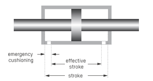
The emergency cushioning serves for the self-protection of the cylinder and the test specimen and is included as standard in the stroke. The effective stroke of the test cylinder is located between the two emergency cushionings.
Bore adjustable to the millimetre
The working areas of the test actuators can be individually designed to meet the respective requirements. This saves on acquisition and operating costs for the required peripherals and achieves high energy efficiency, e.g. in terms of drive and cooling capacity.
Hänchen test hydraulic actuator series
Just right. Really good.
Which cylinder type is the right one for your requirement? The performance chart is used for orientation and describes the dynamic movement of a hydraulic drive during a sinusoidal oscillation. The performance classes of the different cylinder types define the possible applications.
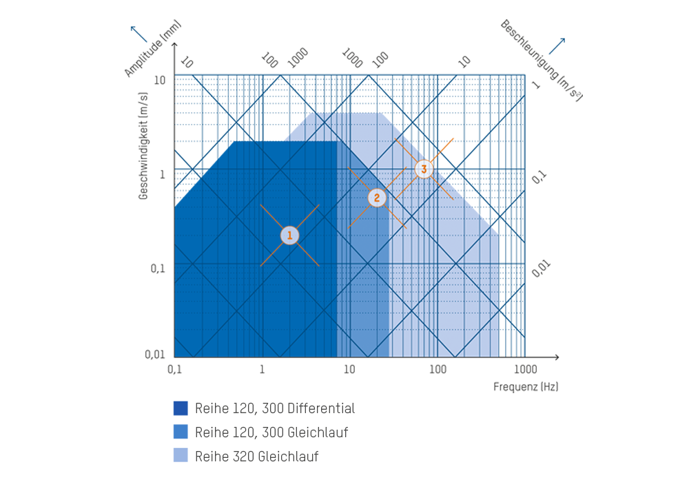
Servo hydraulic actuators of series 120 and 300: slim test actuators for simple testing tasks in typical Hänchen quality - high, honed surface quality, geometric accuracy of the components and matched sealing elements - these servo hydraulic cylinders meet the highest technical requirements, for safe and reliably controlled drives.
Use our product configurator HÄKO for assistance with the design and calculation of your test actuator.
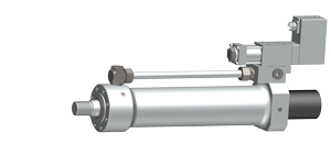
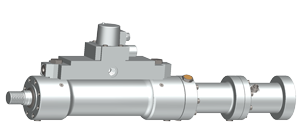
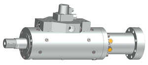
| Examples in the performance chart |
 |
 |
 |
 Series 120, 300 Series 120, 300 Single-rod |
 Series 120, 300 Series 120, 300Double-rod |
series  320 320Double-rod |
|
| Frequency (Hz) | 2 | 20 | 70 |
| Amplitude (mm) | 16 | 4 | 2,3 |
| Speed (m/s) | 0,2 | 0,5 | 1 |
| acceleration (m/s2) | 3 | 63 | 440 |
Limit values in the performance chart without considering on-site restrictions such as port size, sealing system, guiding system or control valve.
Calculation of the test actuator
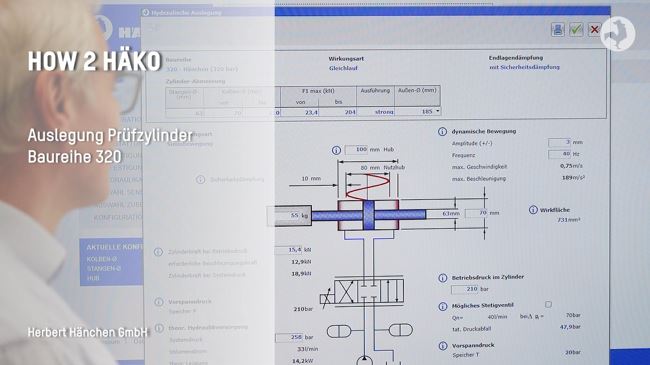
Sinusoidal design in HäKo
Using our HäKo product configurator, you can design test actuators as well as round or servo hydraulic actuator (double-rod) using a sinusoidal calculation diagram.
The video explains in detail how to use the tool for designing the sine movement.
Calculation of the test actuator
Sinusoidal design in HäKo
Using our HäKo product configurator, you can design test actuators as well as round or servo hydraulic actuator (double-rod) using a sinusoidal calculation diagram.
The video explains in detail how to use the tool for designing the sine movement.
The video explains the sinusoidal movement design tool in detail.
Subtitles in your language:
You can activate subtitles by pressing the "c" key or by clicking the button in the top right corner of the video. You can translate them into your language via the settings (gear icon).
Lateral force design
Lateral forces on the piston rod for test cylinders of the 320 series
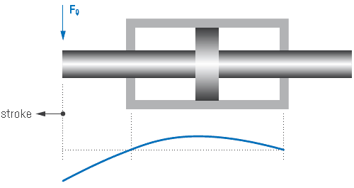
The magnitude of the permissible lateral forces is mainly determined by the rod diameter, the guiding system and the cylinder stroke. This results in different values depending on the stroke position. The permissible lateral force in the retracted end position is always greater than in the extended position. For test cylinders with longer strokes, the choice of sealing and guiding systems is of minor importance with regard to lateral force absorption.
A quick overview can be found in the table below Technical data depending on the nominal force
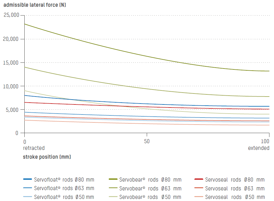
The exact lateral force curves for each dimension can be found in our Hänchen Configurator HÄKO under >> Test actuator >> Equipment
The exact lateral force curves for each dimension can be found in our Hänchen Configurator HÄKO under >> Test actuator >> Equipment
The exact lateral force curves for each dimension can be found in our Hänchen Configurator HÄKO under >> Test actuator >> Equipment
The exact lateral force curves for each dimension can be found in our Hänchen Configurator HÄKO under >> Test actuator >> Equipment
The exact lateral force curves for each dimension can be found in our Hänchen Configurator HÄKO under >> Test actuator >> Equipment
The exact lateral force curves for each dimension can be found in our Hänchen Configurator HÄKO under >> Test actuator >> Equipment
Cover design for servo hydraulic test actuators
Sealing and guiding system in the cover
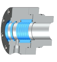
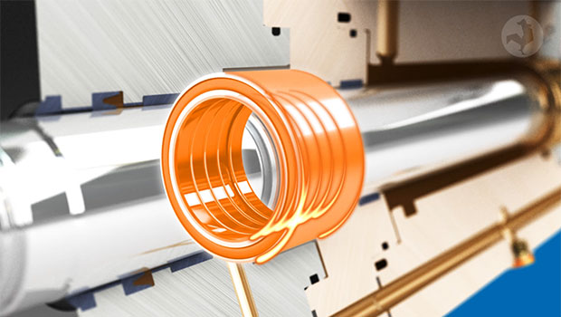
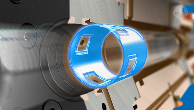
In a dynamic test environment, free-moving hydraulic cylinders with low stick-slip are required. Hänchen offers three versions of test actuators that are particularly low-friction. High manufacturing accuracy with little guide clearance guarantees wear-free use and thus a long service life.
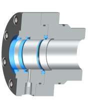
| Guiding system cover | PTFE wear rings = contacting guide elements |
| Sealing system cover |
Servoseal®, lip seal, wiper ring |
| Operating limits |
Speed: 4 m/s Temperature: 80 °C Friction: pressure-independent |
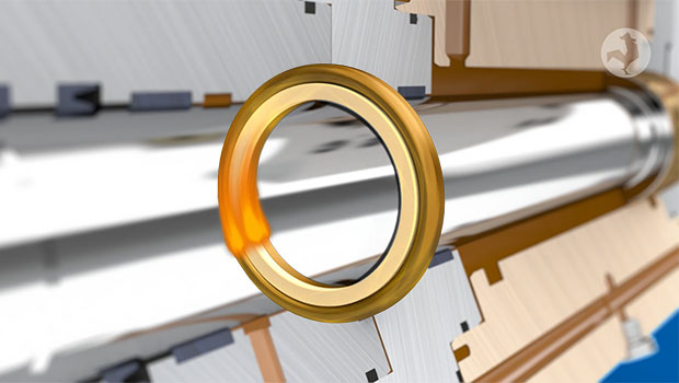
| Guiding system cover | PTFE wear rings = contacting guide elements |
| Sealing system cover |
floating gap seal, functional oil seal, wiper ring |
| Operating limits |
Speed: 4 m/s |
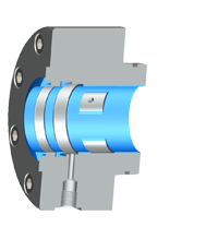
| Guiding system cover | PTFE wear rings = contacting guide elements |
| Sealing system cover |
Functional oil seal, wiper ring |
| Operating limits |
Speed: 4 m/s |
Hydraulic design
Flow rate in test cylinders
When sizing the required flow rate, the gap seals used in the test actuator must be taken into account. In the cover, this is the functional oil flow required for the Servofloat
Special feature at Hänchen: For very friction-sensitive applications with small amplitudes, we offer the specially developed Servoseal
Functional oil flow in covers
Gap seals work with a functional oil flow, which is discharged pressureless into the tank via the leak oil port. It must not be sucked off.
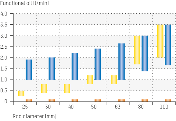
 Servocop®, Servoseal®
 Servofloat®
 Servobear®
Reference values apply to one cover at 210 bar chamber pressure (working pressure), fluid ISO VG 46 at 55 °C.
Leak oil diagram on the piston
In addition to the selected cover type, the right piston design is also crucial for the dynamic movement of the cylinder.
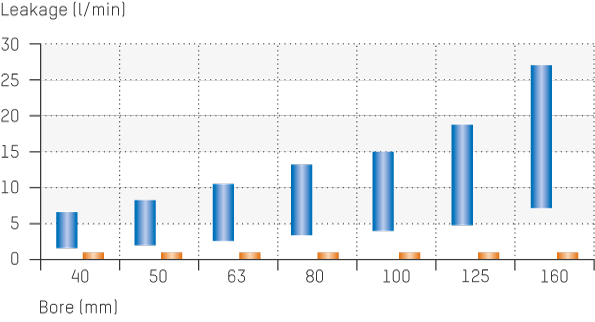
Rectangular compact seal, Servoseal® Gap seal
Reference values apply for 210 bar differential pressure at the piston,
fluid ISO VG 46 at 55 °C.
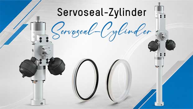
Servoseal cylinder
The modern method of testing
By using our Servoseal® seals on the piston and cover, the test actuators gain new advantages:
- no leakage at the piston
- no functional oil required for the operation of a hydrostatic bearing or floating gap seal
- for stroke lengths from 200 mm, comparable lateral force values to hydrostatic systems
For tests with a frequency of up to 25 Hz, you can also choose the Servoseal cylinder in the 300 series. This provides you with a slender, cost-effective test actuator.
The modern method of testing
By using our Servoseal® seals on the piston and cover, the test actuators gain new advantages:
- no leakage at the piston
- no functional oil required for the operation of a hydrostatic bearing or floating gap seal
- for stroke lengths from 200 mm, comparable lateral force values to hydrostatic systems
For tests with a frequency up to 25 Hz, you can also choose the Servoseal cylinder from the 300 series. This provides you with a slim, cost-effective test actuator.
Technical data hydraulic cylinder
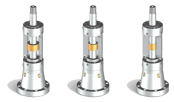
Test actuator of series 320
According to the rod diameter
Type of effect: Double-rod cylinder | Sealing systems: Servoseal®, Servofloat®, functional oil seal (Servobear®) | Speeds: Up to 4 m/s
| Rod Ø (mm) |
Type |
Bore (mm) |
Force (kN) 210 bar |
Force (kN) 320 bar |
Stroke (mm) |
| 25 | strong | 28 – 45 | 2.6 – 23.1 | 4.0 – 35.2 | 50 – 170 |
| 30 | strong | 34 – 55 | 4.2 – 35.0 | 6.4 – 53.4 | 50 – 220 |
| 40 | strong | 45 – 70 | 7.0 – 54.4 | 10.7 – 82.9 | 50 – 270 |
| 50 | strong | 56 – 80 | 10.5 – 64.3 | 16.0 – 98.0 | 50 – 450 |
| 63 | strong | 70 – 110 | 15.4 – 134 | 23.4 – 204 | 50 – 450 |
| 80 | slim | 90 – 120 | 28.0 – 132 | 42.7 – 201 | 50 – 450 |
| 80 | strong | 90 – 150 | 28.0 – 266 | 42.7 – 404 | 50 – 450 |
| 100 | slim | 110 – 150 | 34.6 – 206 | 52.8 – 314 | 50 – 450 |
| 100 | strong | 110 – 175 | 34.6 – 340 | 52.8 – 518 | 50 – 450 |
| 125 | slim | 140 – 175 | 65.6 – 247 | 100 – 377 | 50 – 450 |
| 125 | strong | 140 – 200 | 65.6 – 402 | 100 – 613 | 50 – 450 |
| 160 | slim | 180 – 220 | 112 – 376 | 171 – 573 | 50 – 450 |
| 160 | strong | 200 – 260 | 238 – 693 | 362 – 1,056 | 50 – 450 |
| 200 | slim | 240 – 280 | 290 – 633 | 442 – 965 | 50 – 450 |
| 200 | strong | 250 – 320 | 371 – 1,029 | 566 – 1,568 | 50 – 350 |
strong: massive construction (e.g. vertical installation)
slim: light construction (e.g. horizontal installation with spherical rod eyes)
According to the nominal force
| Nominal force (kN) |
Design |
Rod Ø (mm) |
Bore (mm) |
Force (kN) 210 bar |
Lateral force when extended (kN) |
||||||||||||
| Stroke 100** | Stroke 250** | |||||||||||||||||
| Servoseal® | Servofloat® | Servobear® | |||||||||||||||
| 4 | light rod normal rod |
25 30 |
30 34 |
4,5 4,2 |
0,31 0,51 |
0,27 0,44 |
0,51 1,0 |
||||||||||
| 6,3 | light rod normal rod |
30 40 |
36 45 |
6,5 7,0 |
0,51 1,6 |
| |
0,57 |
0,44 1,5 |
| |
0,54 |
1.0 2.5 |
| |
0,67 |
||||
| 10 | light rod normal rod* |
30 40 |
39 47 |
10,2 10,0 |
0,51 1,6 |
| |
0,57 |
0,44 1,5 |
| |
0,54 |
1.0 2.5 |
| |
0,67 |
||||
| 16 | light rod normal rod* reinforced rod |
30 40 50 |
44 51 59 |
17,1 16,5 16,2 |
0.51 1.6 2.8 |
| | |
0,57 1,6 |
0.44 1.5 2.4 |
| | |
0,54 1,2 |
1.0 2.5 4.6 |
| | |
0,67 1,2 |
||||
| 25 | light rod* normal rod reinforced rod |
40 50 63 |
56 64 74 |
25,3 26,3 24,9 |
1.6 2.8 3.8 |
| | | |
0.57 1.6 3.2 |
1.5 2.4 3.6 |
| | | |
0.54 1.2 2.9 |
2.5 4.6 7.8 |
| | | |
0.67 1.2 2.3 |
||||
| 40 | light rod normal rod* reinforced rod |
40 50 63 |
64 70 80 |
41,2 39,6 40,1 |
1.6 2.8 3.8 |
| | | |
0.57 1.6 3.2 |
1.5 2.4 3.6 |
| | | |
0.54 1.2 2.9 |
2.5 4.6 7.8 |
| | | |
0.67 1.2 2.3 |
||||
| 63 | light rod* normal rod reinforced rod |
50 63 80 |
80 88 101 |
64,3 62,3 62,7 |
2.8 3.8 6.7 |
| | | |
1.6 3.2 4.5 |
2.4 3.6 6.4 |
| | | |
1.2 2.9 5.1 |
4.6 7.8 13.3 |
| | | |
1.2 2.3 4.4 |
||||
| 100 | light rod normal rod* reinforced rod |
63 80 100 |
100 112 127 |
99,5 101,3 101,1 |
3.8 6.7 11.1 |
| | | |
3.2 4.5 9.7 |
3.6 6.4 10.3 |
| | | |
2.9 5.1 8.7 |
7.8 13.3 24.9 |
| | | |
2.3 4.4 9.7 |
||||
| 160 | light rod* normal rod reinforced rod |
80 100 125 |
127 140 160 |
160,5 158,3 164,5 |
6.7 11.0 16.2 |
| | | |
4.5 9.7 15.9 |
6.4 10.3 15.1 |
| | | |
5.1 8.7 14.6 |
13.3 24.9 49.5 |
| | | |
4.4 9.7 23.9 |
||||
| 250 | light rod normal rod* reinforced rod |
100 125 160 |
160 175 202 |
257,3 247,4 250,8 |
11.0 16.2 24.7 |
| | | |
9.7 15.9 24.0 |
10.3 15.1 22.1 |
| | | |
8.7 14.9 22.7 |
24.9 49.5 81.6 |
| | | |
9.7 23.9 42.2 |
||||
| 400 | light rod* normal rod reinforced rod |
125 160 200 |
200 225 225 |
402,0 412,7 412,7 |
16.2 24.7 31.7 |
| | | |
15.9 24.0 30.6 |
15.1 22.1 |
| | | |
14.6 22.7 |
49.5 81.6 99.1 |
| | | |
23.9 42.2 58.4 |
||||
| 630 | normal rod* reinforced rod |
160 200 |
225 280 |
650,3 633,3 |
24.7 31.7 |
| | |
24.0 30.6 |
22,1 | | | |
22,7 | 81.6 99.1 |
| | |
42.4 58.4 |
||||
| 1.000 | normal rod* | 200 | 320 | 1.029,2 | 31,7 | | | 30,6 | | | 99,1 | | | 58,4 | ||||||
The assignment of the piston to the nominal force is for orientation purposes. For optimised design taking into account hydraulics, dynamics or weight, please use the calculation in our HÄKO product configurator.
* Reference to market-standard dimensions such as the Schenck actuators.
** Mechanical guiding systems in Servoseal® and Servofloat® are limited by the permissible surface pressure, but can absorb very high lateral forces and deflections with long strokes. Hydrostatic bearings (Servobear®) are characterised by a very high bearing and lateral force capacity, especially with short strokes.
FAQ - Test actuator
Technical questions regarding application
How does the bore influence the required flow rate?
The working area, together with the hydraulic pressure, determines the generated force, and together with the travel speed, the required flow rate. At Hänchen, customers can precisely adapt the bore to the actual testing application. This avoids unnecessary oil movement, allowing pumps, valves, piping, and cooling systems to often be designed smaller and more economically.
How does the Hänchen modular system facilitate changing test setups?
Mounting and accessories such as spherical rod eyes, force transducers, position transducers, mounting plates, accumulators, and control valves can be used for cylinders of varying forces. Therefore, these components do not need to be re-procured for each test actuator during changing test series. This shortens changeover times, increases the utilization of the test area, and reduces storage and investment costs.
How does a Hänchen test actuator operate without an external leak oil pump?
The sealing and guiding systems are designed so that no separate leak oil pump is required. With Servofloat®, pressure is relieved contact-free via a narrow throttle gap; Servobear® internally supplies the hydrostatic bearing using the existing system pressure. In both designs, the functional oil flow is returned to the tank without pressure or pre-pressurized up to 5 bar and must not be suctioned off!
This reduces installation effort, space requirements, and maintenance, while eliminating the energy consumption of an additional pump, thereby lowering both investment and operating costs.
For which types of tests are the hydraulic test cylinders primarily designed?
Hänchen test actuators, also known as hydraulic test cylinders, are ideal for dynamic and high-frequency material and component testing. Typical applications include service life and fatigue tests, component tests in the automotive and aerospace industries, as well as demanding simulations in research and development. Their precision and robustness enable realistic load tests.
What does stick-slip mean in a test actuator?
Stick-slip refers to an abrupt change between sticking and sliding. In test stands, this effect distorts force, position, and acceleration signals, complicating precise control. Low-friction or contact-free sealing and guiding systems reduce this effect, enabling smoother, more reproducible movements.
Why does Hänchen offer three different sealing and guide concepts?
Testing applications present highly diverse requirements regarding friction, leakage, temperature, and lateral force absorption. With Servoseal®, Servofloat®, and Servobear® , the system can be specifically tailored to these priorities, rather than employing a technical compromise for all applications. This provides customers with a needs-based solution that is neither unnecessarily complex nor undersized for the task.
Advantages with Hänchen
Provider of test actuators and more
How exactly can I save costs when setting up my test stand by using a Hänchen test actuator?
-
You save on multiple levels:
- The costs for an external leak oil pump, its piping, and control are eliminated.
- The cylinder's working area can be optimized as standard, allowing you to use a smaller, more cost-effective hydraulic power unit and smaller valves, which reduces both investment and operating costs.
- The modular system allows accessories such as force transducers or valves to be reused for cylinders of different force classes. This significantly lowers investment costs for changing test setups.
What is the advantage of the Servoseal® sealing system with a carbon retaining ring?
-
The Servoseal® system provides dynamic sealing and, through its integrated carbon retaining ring, prevents excessive pressure on the seal. This avoids wear, ensures a low-friction response, and makes the cylinder more efficient. A decisive advantage is that, unlike hydrostatic bearings, no separate functional oil is required.
Does Hänchen also offer complete test systems?
-
Hänchen has one of the largest test actuator ranges on the market and acts not only as a component manufacturer. Upon request, the company also realises complete, individual test machines and system solutions. Customers thus benefit from a perfectly coordinated drive solution from a single source.
How does Hänchen support me even after purchasing a cylinder?
-
Hänchen ensures a long-term supply of spare parts, even for products decades old; the serial number is sufficient for this. Furthermore, the company offers comprehensive services such as repairs and technical consulting. The high level of vertical integration and detailed knowledge of every product supplied guarantee competent and fast support throughout the entire service life cycle.