
Locking unit Ratio-Clamp®
A clamping unit for rod locking
The patented locking unit Ratio-Clamp® fixes round rods without energy supply for an unlimited time.
The clamping unit is used worldwide as a safety component in personal and plant protection, as a holding element for tools and workpieces, and as rod locking in production processes or testing procedures.
Advantages of the locking units:
- Can be used horizontally and vertically
- Direction-independent, can be loaded in tension and compression
- Clamping force acts immediately, without further movement of the rod
- Releasing the clamping by hydraulic pressure, without return movement of the rod

- Holding load up to 2,000 kN
- Proven product at Hänchen since 1965
- Positionally accurate locking
- Securely holding raised loads
- Round rods up to Ø 300 mm
- 100% made in Germany
Application areas of locking units
Efficient rod lockings
There are many situations in which rods must be held in a specific position: Here are a few practical examples where our rod locking systems securely fix the axles.
- Grinding machine > Production
During the production of ICE railway sleepers, extremely large and heavy concrete workpieces must be positioned precisely and safely for grinding to an accuracy of 0.01 mm. The hydraulic cylinders and Ratio-Clamp® clamping units are designed precisely for these requirements.
- Aviation > Test engineering
The structures for aircraft tests are sophisticated down to the last detail. Hänchen test actuators are used in various test areas to simulate environmental conditions and loads during the individual flight phases. To protect the elaborately manufactured and expensive systems, Ratio-Clamp® rod lockings are used.
- Presses > Production
Locking cylinders from Hänchen guarantee safe movement of the press. Clamping units ensure safety during the pressing process in compression and injection moulding presses for the production of moulded parts made of synthetic materials and rubber in accordance with EN 289.
- Railway technology > Maintenance
For maintenance purposes, trains must be fixed in the raised position - the Ratio-Clamp® is ideally suited for this. The locking units hold the train securely in position until the work is completed and it can return to the rails.
- Profiling machine > Production
In the production of metal profiles, Hänchen locking units guarantee precise machining and consistent quality. During the production process, they secure the machining of the profiles by locking the shaping tools. Ecologically sound and efficient, purely with spring force.
The locking unit in detail
The Ratio-Clamp® locking unit works mechanically according to the functional principle of frictional contact. The force stored in disc springs is deflected via cones and clamps the rod by means of friction.


- Locking and securing the load
If the release pressure drops, the force stored in the springs is released and causes the rod to clamp. Thus the load is secured and the Ratio-Clamp® is ready to take over the load.
- Load
Loading is possible immediately after clamping. No axial movement of the rod is required. In the clamped state, the forces can be kept free of play in both directions.
- Releasing
The locking piston moves against the spring power by hydraulically releasing pressure and releases the clamping force. The rod can be moved in both directions.
- Overload
Short-term overloading with slipping of the rod is possible without damaging it or the clamping unit.
The video shows the functional principle of the clamping unit Ratio-Clamp® using the example of a gantry milling machine.
These locking units from Hänchen can be used both for exact locking and for securing against unwanted movements.
- Fixing round rods of all types, in any position
- Clamps from standstill, also for braking from movement in the event of an occasional accident
- Clamping force without energy supply for an unlimited time
- In the event of (un)controlled pressure drop, emergency shutdown, power failure or system damage
- Fixes axles precisely, even when external forces act on the rod

Energy efficiency and precision for all cases
Locking unit Ratio-Clamp®
Do you have an application where a round rod needs to be held in a defined position? There are several ways to achieve this: by electronic control, shutting off all ports, locking with pivot pins, or by using locking units.
The clamping unit Ratio-Clamp® scores with numerous advantages.
- Stepless clamping without energy supply
- Fixes exactly in any position
- Holds position with temperature fluctuations
- Saving of energy costs by clamping with spring force
Comparison of fixing options for round rods
| Electronic control |
Shut off ports |
Pivot pin locking |
Clamping unit Ratio-Clamp® |
|
| Energy efficiency | – | + | + | + |
| Positional accuracy | + | – | + | + |
| Independence from external influences |
+ | – | + | + |
| Effort | – | + | – | + |
| Flexible positioning | + | + | – | + |
Advantage of the Ratio-Clamp® locking unit: It holds the piston rod in any position without hydraulic or electrical energy supply.
Case study: Energy consumption for holding a piston rod
A hydraulic cylinder with a bore of 80 mm is moved at 150 bar with a speed of 0.5 m/s. The required drive power is 38 kW.
With electronic control using a controlled pump, there is a power loss of approx. 1.25 kW from the controlled pump. In addition, losses at the control valve of approx. 1.25 kW are to be expected. In this example, the total power loss of the controlled drive is 2.5 kW. With a holding time of 5,000 hours per year, the energy loss is over 12,000 kWh.
With the locking unit Ratio-Clamp® , the energy loss is 0 kWh during the holding process.

ROD LOCKING FOR TEST APPLICATIONS
For very sensitive or highly dynamic applications, we recommend the sealing system "pressure piston seal". The sliding friction here is extremely low and independent of the releasing pressure. See description in the next section under "Sealing system"
Equipment
Features of a clamping unit
- Release pressure
Basic design
The basic release pressure required for releasing the clamping unit is between the minimum pressure and the maximum admissible pressure of 160 bar.
Reduced design
For application cases with low supply pressure, a version designed with reduced release pressure is available.- Certification
TÜV certification
Every Ratio-Clamp® locking unit is type-tested by TÜV SÜD.
DGUV Test
This clamping unit bears the DGUV Test certificate (Testing and Certification System of the German Social Accident Insurance). For use as a safety component, a B10D value in accordance with EN ISO 13849-1 is available for the Ratio-Clamp®. The 2-fold safety factor required by DGUV for the maximum holding load is already accounted for in the load specifications of the technical data.
Learn on about the Ratio-Clamp® clamping unit with DGUV Test certification
- Interlock
With spring force
Normally, the rod locking is achieved via the energy stored in springs. This allows the rod to be held for an unlimited time without energy supply.
Hydraulic
If very high holding loads are required, the clamping unit can also be locked hydraulically. It is released as usual using hydraulic pressure.- Sealing system
Servocop®: compact seal, lip seal, wiper ring
In its basic design, the Ratio-Clamp locking unit operates with the friction-optimised Servocop® sealing system. In this system, the primary seal is applied to the rod. The maximum rod speed is 1 m/s.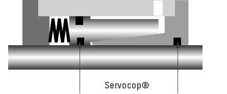
Pressure piston seal, lip seal, wiper ring
For very sensitive applications, we recommend the design with pressure piston seal, where no pressurised seal touches the rod. Thus, the sliding friction is very low and remains constant regardless of the release pressure. The maximum speed of the rod is 2 m/s.
Quality thought further.
- Hydraulic cylinder
-
can be mounted on Hänchen industrial hydraulic cylinders or standard cylinders DIN/ISO according to ISO 6020-1, ISO 6020-2 and third-party products via a fixed flange. For this purpose, the piston rod must be extended according to the length of the clamping unit. For separate mounting, the clamping unit can also be loosely mounted with the aid of a collar flange to compensate for an axial offset.

- Proximity switch
-
The respective status – rod locked or released – can be queried via inductive proximity switches. When using the Ratio-Clamp® as a safety component or with required DGUV Test certification, the installation of a proximity switch with diagnostic output is mandatory. This also monitors the function of the switch and the supply line.

- Control block
-
A control block is used when the locking unit is mounted on a hydraulic cylinder. It ensures a consistent, functional control and reduces the complexity of the control system.
When actuating a Ratio-Clamp®, it must first be released by applying pressure to the release port; only then may the rod be moved. When using a clamping unit in conjunction with a hydraulic cylinder, this can be achieved through hydraulic sequence control or electronic monitoring. For instance, sensors in an electronic control system can measure the load on vertically installed cylinders to build up a counter-pressure. This prevents the rod from jerking during release.
This can also be achieved with a hydraulic control block: first the release pressure is built up, then the cylinder is pressurised. Matching valves locks the pressure in the cylinder so that the Ratio-Clamp® can be unlocked almost without jolts even when handling vertical loads.

- Functional rod
-
The round rod to be clamped should have a hard surface and must meet the minimum requirements when installing the Ratio-Clamp®. A honed rod is recommended.
At Hänchen you can order a suitable functional rod directly and configure it via the HäKo product configurator.

Technical data of the locking unit
hydraulically released
- For all round rods with a hard surface
- Loadable regardless of direction
- Factory check of the Ratio-Clamp® required after 2 million switching cycles
- Max. rod speed in the released state: 1 m/s with Servocop®, 2 m/s with pressure piston seal
- Max. release pressure: 160 bar
- Working temperature: -30 °C to +80 °C
- Fluids: Mineral oils or HFC*, others such as water or Skydrol® on request
| RATIO-CLAMP® |
RATIO-CLAMP® REDUCED RELEASE PRESSURE |
RATIO-CLAMP® PRESSURE PISTON SEAL |
||||||
| + Release pressure + Locking + Sealing system + Certification |
Basic design With spring force Servocop® TÜV |
Reduced design With spring force Servocop® TÜV |
Basic design With spring force Pressure piston seal TÜV |
|||||
| Rod-Ø (mm) |
Holding load max. (kN) |
Release pressure min. (bar) |
Holding load max. (kN) |
Release pressure min. (bar) |
Holding load max. (kN) |
Release pressure min. (bar) |
||
| 16 | 10 | 60 | 8 | 50 | ||||
| 18 | 12,5 | 55 | 8 | 35 | 12,5 | 75 | ||
| 20 | 14 | 55 | 9 | 40 | 14 | 75 | ||
| 22 | 17 | 70 | 12 | 45 | 17 | 90 | ||
| 25 | 20 | 70 | 15 | 50 | 20 | 90 | ||
| 28 | 31,5 | 90 | 25 | 65 | 31,5 | 120 | ||
| 30 | 40 | 105 | 30 | 75 | 40 | 135 | ||
| 32 | 40 | 60 | 30 | 45 | 40 | 90 | ||
| 36 | 45 | 75 | 32 | 50 | 45 | 100 | ||
| 40 | 50 | 80 | 38 | 55 | 50 | 100 | ||
| 45 | 65 | 70 | 45 | 50 | 65 | 90 | ||
| 50 | 80 | 90 | 55 | 60 | 80 | 110 | ||
| 56 | 90 | 75 | 60 | 50 | 90 | 100 | ||
| 60 | 100 | 75 | 70 | 55 | 100 | 100 | ||
| 63 | 100 | 85 | 60 | 55 | 100 | 110 | ||
| 70 | 140 | 80 | 100 | 55 | 140 | 110 | ||
| 80 | 180 | 90 | 130 | 65 | 180 | 110 | ||
| 90 | 200 | 65 | 200 | 85 | ||||
| 100 | 250 | 75 | 250 | 95 | ||||
| 110 | 300 | 65 | 300 | 90 | ||||
| 120 | 330 | 70 | 330 | 90 | ||||
| 125 | 350 | 75 | 350 | 90 | ||||
| 140 | 450 | 65 | ||||||
| 160 | 750 | 90 | ||||||
Further holding loads & rod Ø on request.
A hydraulic locking mechanism is possible up to 2,000 kN holding load and rod Ø 300 mm.
*The specified values apply to operation with mineral oil. When using other fluids such as HFC, the holding load may differ.
FAQ - Clamping Unit Locking Unit
Questions on mechanical engineering fundamentals
- What is a locking unit?
A clamping unit or locking unit is a machine element that holds a round rod or piston rod in a defined position. This rod locking fixes the rod indefinitely without external energy supply. In mechanical engineering, a clamping unit is used when axles, workpieces, tools, or loads must be securely held, precisely locked in position, or protected against unintentional movement. Typical applications include machine tools, test stands, presses, maintenance plants, or production processes.
- How can I clamp a hydraulic cylinder?
Hydraulic cylinders can be designed as clamping or locking cylinders, i.e. a clamping system is structurally integrated. Alternatively, hydraulic clamping can be attached to the head of the cylinder via a flange, which clamps the piston rod as soon as the hydraulic pressure drops to 0 bar.
- How does a clamping unit or locking unit work?
A clamping unit or locking unit is a safety-relevant additional module that mechanically clamps and holds the piston rod of a hydraulic cylinder, as well as any round rods. In most cases, it operates by holding the clamping open via pneumatic or hydraulic pressure. In the event of a pressure drop, the rod is clamped by frictional contact via spring force within a few milliseconds. The holding load of the locking unit remains stable for an unlimited period. It is used, for example, as a safety element in case of power failure or for energy saving during power shutdown.
- What options are there for a load holding function?
A load holding function can be implemented in various ways. Loads can be held by:
- hydraulically shut off ⇒ non-return valve or lowering brake valve
- mechanically lock ⇒ pivot pin or toothing
- electronically controlled ⇒ hold in position in the control circuit
- clamping element like the Ratio-Clamp® locking unit ⇒ clamp rod by frictional contact
- Why is my axis sinking despite the load control valve?
Non-return valves and counterbalance valves can hold hydraulic loads, but they depend on factors such as oil compressibility, temperature changes, viscosity, and leakage at seals. As a result, an axle can slowly lower/sink despite the valve. A mechanical locking unit like the Ratio-Clamp® holds the rod by frictional contact, making it independent of hydraulic or electrical energy. This is particularly advantageous when an axle needs to be held precisely in position for an extended period or when lowering/sinking must be avoided under all circumstances.
- What safety functions can a hydraulic clamping unit perform (emergency switch-off, power failure, etc.)?
A spring-actuated locking unit can serve as an important component of the safety concept by immediately blocking movements in an emergency. The Ratio-Clamp® is designed to move into the “safe” position and clamp the round rod in the event of a pressure drop or power failure. In the clamped state, forces in both directions are reliably held, even if the hydraulic supply fails. For gravity-loaded axles and safety-relevant applications, it must be checked whether a version with DGUV test certification and a B10D value according to EN ISO 13849-1 is required. For this purpose, there is also the safety catcher specifically developed for vertical axles.
In combination with suitable valve and control blocks from Hänchen, emergency switch-off functions and controlled holding or securing functions can be implemented. For operators, this means: higher personal protection, less risk of damage to machinery and workpieces, and a reliable safety concept.
Technical questions regarding the use
of the locking unit
- What is a clamping unit typically used for?
-
A clamping unit is used to hold, secure, or precisely lock a linear axle in position. Typical applications in mechanical engineering include machine tools where axles or feed movements must be precisely fixed in a position, e.g., in profiling machines, or where heavy workpieces need to be fixed, e.g., in grinding machines. In test stands, e.g., for airfoils, landing gear, or structural tests, clamping units secure test specimens against unwanted movements and relieve the cylinders. Further applications include lifting and clamping devices, e.g., in presses for holding gravity-loaded axles.
- When do I choose a safety catcher and when a locking unit?
-
Both the safety catcher and the locking unit operate on the principle of frictional contact.
Safety catcher:
⇒ Specifically for securing gravity-loaded, vertical axles
Advantage: Self-energizing principle and thus very high holding loads
Note: A short relief stroke is required to release the clamping if the load has been taken over by the safety catcher.Locking unit:
⇒ Universal solution for general holding tasks in any mounting position (vertical and horizontal).
Advantage: Releases the load or position precisely at the clamped point without the need to move the axle. - What role do friction, speed, and the sealing system play in the design?
-
For dynamic or sensitive applications, the clamping unit must match the motion profile of the hydraulic cylinder. Hänchen offers the Ratio-Clamp® with, among other features, the friction-optimized Servocop® sealing system, as well as with a pressure piston seal for particularly low sliding friction that is independent of the release pressure. The maximum rod speed is 1 m/s with Servocop® and 2 m/s with a pressure piston seal. This selection is particularly important for test tasks to ensure that holding, traversing, and regulating are not impaired by unwanted friction. For test actuators with friction-free sealing systems, the locking unit is mounted at the rear.
- Are there locking units for higher forces?
-
The release of the locking unit can be operated pneumatically or hydraulically. Pneumatic locking units are available on the market up to a maximum of 40 kN. For higher forces, hydraulic locking units are suitable, which can range up to 750 kN and more.
If the safety and energy-saving function is not required, a clamping unit that is hydraulically locked is also possible; this can hold up to 2,000 kN.
- What are typical sources of error when using locking units?
-
A common source of error is an incorrect switching sequence: the rod may only be moved when the clamping unit is completely released. Unsuitable rod surfaces or a missing control block in more complex hydraulic systems are also critical. For vertical axles, it must also be prevented that the load gives way abruptly when released. A precise design of the clamping unit, the hydraulic circuit, and condition monitoring increases operational safety and reduces maintenance risks.
- How is a locking unit integrated into a hydraulic cylinder system?
-
The Ratio-Clamp® clamping units are mounted on Hänchen hydraulic cylinders or third-party brands, as well as on standard cylinder DIN/ISO according to ISO 6020-1 and ISO 6020-2. Key interfaces include the rod diameter, the mounting geometry, typically mounting via a fixed flange. For separate (parallel) mounting, a collar flange can be used to compensate for axial misalignment. It is important that the round rod to be clamped has a suitable hard surface. When combined with a hydraulic cylinder, a suitable control block reduces the circuit complexity and ensures the correct sequence for unlocking and traversing.