
Safety catcher in machines
Fall protection in mechanical engineering for vertical axles
The safety catcher is used for clamping round rods in vertical axles.
It ensures maximum safety and reliability – whether for stepless securing of loads at a standstill, as a safety component for gravity-loaded axles in case of emergency, or for effective fall protection in mechanical engineering.
The safety catcher locked according to a self-energizing principle is available in pressure or tension-activated versions. It is unlocked by hydraulic or pneumatic pressure.

- Safety of people and machine
- Clamping force without energy supply
- For vertical use
- Pneumatic or hydraulic
- Holding load through self-reinforcement principle
- DGUV-Test certified
Use and application of the safety catcher
The safety solution for people and machine
The safety catcher is based on our experience with clamping units of the Ratio Clamp® design, which has grown since 1965. We have specifically developed this proven technology to ensure maximum safety in applications on vertical, gravity-loaded axles. This allows us to provide a higher clamping force in an emergency.
- Fixing round rods of all types, in any position
- Clamps from standstill, also for braking from movement in the event of an occasional accident
- Clamping force without energy supply for an unlimited time
- Fixes axles precisely in the event of power failure, drive or control errors

- Presses & punching machines: Prevents lowering/sinking of the upper part, protects tools and operating personnel
- Machine tools: Reliably secures heavy vertical axles and spindles against falling.
- Robotics & portals: Holds tools and loads securely in position, even in the event of drive failure
- Intralogistics & lifts: Guarantees safety for people and goods in lifting systems
Functional principle of the safety catcher
The clamping unit for mechanical restraint device
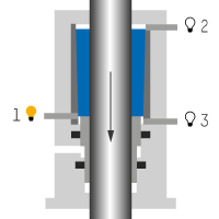
The safety catcher operates mechanically according to the functional principle of frictional contact. When unpressurised, the holding load builds up via the conical clamping system as the load sinks. The self-energizing principle comes into effect, locking the rod.

Securing load
When the release pressure drops, the spring-loaded clamping segments rest against the rod to be clamped. The resulting friction force secures the load, and the safety catcher is ready to take over the load.
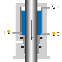
Locking, take over load
If the rod to be clamped moves in the direction of the load, the clamping segments shift due to friction until they reach the internal stop. This leads to a self-reinforcing locking of the system. As a result, the holding load builds up, and the load is taken over.

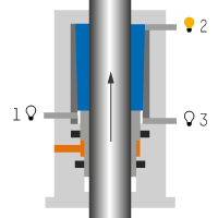
Releasing
Hydraulic or pneumatic release pressure pushes the release piston, together with the clamping segments, upward from the “securing load” state into the released position.
In the locked state, in addition to the release pressure, an external force must be applied to the clamped rod in the opposite direction to the load.Load and overload
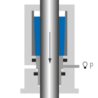
Once the load is taken over, the rod holds securely as long as the maximum permissible holding load is not exceeded.
An overload causing the rod to slip through may occasionally occur without damaging it or the safety catcher.
Mounting the safety catcher
Mounting compressive load or tensile load


Fixed mounting flange
In addition to the centering collar permanently mounted on the safety catcher, a fixed flange can be used. When in use, make sure that the safety catcher is installed without any stress.
Loose mounting flange
In addition to the centering collar permanently mounted on the safety catcher, a loose flange can be used. This enables both radial and vertical movement compensation.

Sensors of the safety catcher
Inductive proximity switches and pressure switches
The safety catcher can optionally be equipped with up to 4 independent sensors: Depending on the required performance level of the machine into which the safety catcher is integrated, the proximity switches can be provided in a redundant version or with a diagnostic output if required.
Technical data of the safety catcher
Released by hydraulic or pneumatic pressure
| SAFETY CATCHER FOR VERTICAL AXLES |
||||||
| + Locking + Certification |
Self-reinforcing DGUV Test |
|||||
| Rod-Ø (mm) |
Permissible load (kN) |
Installation length1 (mm) |
Installation length2 (mm) |
Installation diameter |
||
| 25 | 10 | 152 | 155 | 71 | ||
| 28 | 15 | 169 | 82 | |||
| 40 | 33 | 211 | 214 | 106 | ||
| 50 | 52 | 264 | 125 | |||
| 56 | 67 | 262 | 265 | 140 | ||
| 63 | 100 | 285 | 290 | 160 | ||
| 70 | 107 | 302 | 172 | |||
| 80 | 133 | 322 | 325 | 194 | ||
1 Compressive load without centering collar
2 Tensile load with centering collar
The values given apply to all fluids.
The holding load of the safety catcher for machines has a safety factor of at least 2, but does not exceed a safety factor of 2.8.
- Compressive load or tensile load
- Hydraulically released: min. 40 bar, max. 250 bar
- Pneumatically released: min. 4 bar, max. 10 bar
- Factory check of the safety catcher required after 2 million switching cycles
- Max. rod speed in the released state: 0.5 m/s
- Working temperature: 0 °C to +60 °C
- Fluids: mineral oils, HFC or compressed air, others on request
Various mounting flanges and sensor technology components are available as accessories. A functional rod with freely configurable piston rod ends can also be configured in the HäKo online product configurator.
FAQ - Clamping unit safety catcher
Questions about mechanical engineering fundamentals
- What is the difference between static clamping and dynamic braking?
-
Static clamping serves to securely hold an already stationary load, as this clamping unit does. Dynamic braking, on the other hand, is the deceleration of a movement. The Hänchen safety catcher is designed and certified for static holding, not for braking from motion.
- What is the significance of a DGUV Test certification for a clamping unit?
-
The DGUV Test certification confirms that the clamping unit is tested as a safety-related component according to European standards such as EN ISO 16092-1/-3 for presses. It simplifies the risk assessment of the overall machine, as the protective function is officially proven.
- What distinguishes the Hänchen clamping unit from hydraulic lock valves?
-
In contrast to hydraulic lock valves (e.g., pilot-operated non-return valves), the Hänchen clamping unit functions purely mechanically and independently of energy. This offers higher safety in the event of pressure drop or leakage and, as a certified component, meets the requirements for a safety catcher without additional redundant systems.
of the safety catcher
- Where is the clamping unit for safety catcher typically used?
The clamping unit - safety catcher is primarily used for securing vertical, gravity-loaded axles in hydraulic systems. Typical applications include presses, lifting devices, and other machines where a load must be securely held in position.
- What requirements must the piston rod meet for the use of the clamping unit?
The clamping unit is designed for use on hard-chrome plated piston rods. This surface finish ensures reliable clamping action and a long service life for the clamping segments and the rod.
- What is the difference between a locking unit and a safety catcher?
The main difference lies in the application purpose and behavior when releasing the clamping.
The safety catcher is a specialized safety component for holding loads on vertical axles. Due to the self-energizing effect during load transfer, it generates enormous forces; a relief stroke is required for release.The locking unit serves as a universal solution for precisely holding axles in any mounting position. It releases the position exactly at the clamped point without the need to move the rod for this purpose.