Installation
Clamping unit: Ratio-Clamp®
Before installation into the machine:
- Inspect the delivery for completeness and damage.
The scope of delivery includes the Hänchen product as ordered by the customer according to the order specifications and confirmed in the order confirmation.
- Remove any installed cover plugs or cover plates used for protection against contamination during transport.
| DANGER! | Danger to life due to failure of the clamping unit!
|
| WARNING! | Risk of injury from tensioned spring elements!
|
| CAUTION! | Risk of injury due to sharp edges and corners!
|
| DANGER! | Risk of injury due to hydraulic pressure!
|
| DANGER! | Danger to life due to improper installation!
|
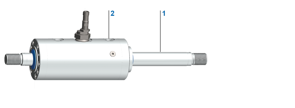
Installation of the Ratio-Clamp® clamping unit with functional rod
|
- Do not disassemble the Ratio-Clamp®; the device is ready for operation.
- Attach the Ratio-Clamp® to the machine.
- Fasten the functional rod to the machine.
- Ratio-Clamp® is operational.
| NOTE | Bring the Ratio-Clamp® clamping unit into the desired position!
|
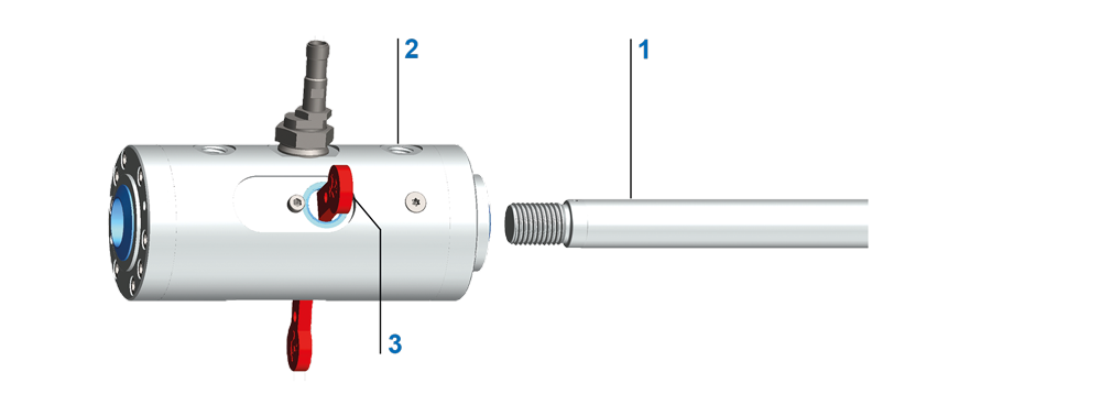
Installation of the Ratio-Clamp® clamping unit with transport rod
|
|
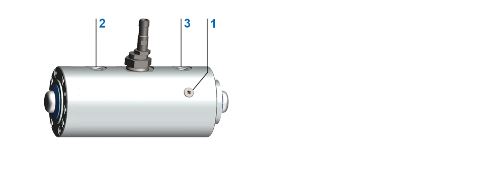
- Loosen screws (2) on the cover by one turn each.
- Cut and remove the marked transport o-ring (3).
- Insert the clamping unit onto the rod to be clamped, with the releasing side EE first.
- Carefully slide the transport rod (1) out of the Ratio-Clamp® with the rod to be clamped.
- Position the Ratio-Clamp® as desired.
- Tighten loosened screws on the cover crosswise until the cover rests flush on the cylinder tube.
- Observe tightening torques according to VDI 2230. Refer to the table under Hydraulic cylinder - Installation.
Installation of the Ratio-Clamp® clamping unit with key in transport position
|
|
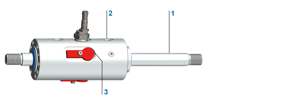
Installation of the Ratio-Clamp® clamping unit with key in operating position
|
|
- Do not disassemble the Ratio-Clamp®; the device is ready for operation.
- Insert the Ratio-Clamp® onto the rod to be clamped, with the releasing side EE first.
- Attach the Ratio-Clamp® to the machine. For this purpose, use the pre-assembled flange or the screws on the release side (EE).
CAUTION: The opposing screws on the leak oil side (L) are under spring preload.
- Attach the rod to be clamped to the machine.
- Hydraulically release the Ratio-Clamp® at port (EE). Observe minimum and maximum pressure.
- Remove the key from the transport position and place it in the operating position. Secure the key with a
screw. - Ratio-Clamp® is operational.
- Ensure that the clamping unit is not filled during the flushing process.
- Connect releasing port EE and leak oil port L of the Ratio-Clamp®.
- Perform venting analogously as described in Hydraulic cylinder - Installation.
Venting screw
|
|
- Vent the Ratio-Clamp® before start-up.
The venting set is available as tools.
When the Ratio-Clamp® is used together with a hydraulic cylinder, observe the following actuation sequence:
- Release the Ratio-Clamp® by applying pressure at the releasing port.
- Move the rod by pressurizing the piston surfaces in the cylinder.
After the rod has reached the desired position:
- Depressurise the A and B ports of the cylinder.
- Depressurize the releasing port of the Ratio-Clamp®.
Ratio-Clamp® is locked.
When using a Hänchen control block connected between the directional valve and the Ratio-Clamp®/cylinder unit, the described sequence occurs automatically. The control block ensures logical and functional control, reducing the circuit engineering effort for the user to a minimum.
| CAUTION! | Malfunctions due to signal errors!
|
To indicate whether the Ratio-Clamp® is locked or released, Hänchen recommends the installation of an inductive proximity switch. Proximity switches operate contact-free and wear-free. The optional additional diagnostic output monitors the function of the switch and the supply line.
Upon delivery, the proximity switch is set to the desired indication according to the documentation (locked or released).
- Check the proximity switch setting as follows: Apply minimum releasing pressure to the Ratio-Clamp® clamping unit.
The switch activates to the desired position.
- If necessary, change the setting of the proximity switch.
Set the proximity switch display to locked as follows:
- Ratio-Clamp® depressurize (pressure < releasing pressure).
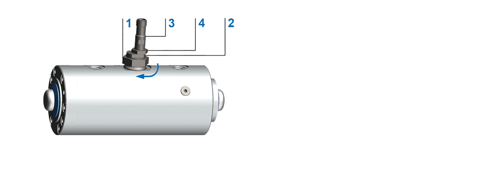
Set the proximity switch to locked
|
|
- Loosen the lock nut (1).
- Turn the eccentric (2) until the proximity switch closes and the indicator light illuminates.
- Tighten lock nut (1) with max. 70 Nm.
- Pressurize Ratio-Clamp® with minimum releasing pressure.
Proximity switch opens. Indicator turns off.
Set the proximity switch display to released as follows:
- Pressurize Ratio-Clamp® with minimum releasing pressure.
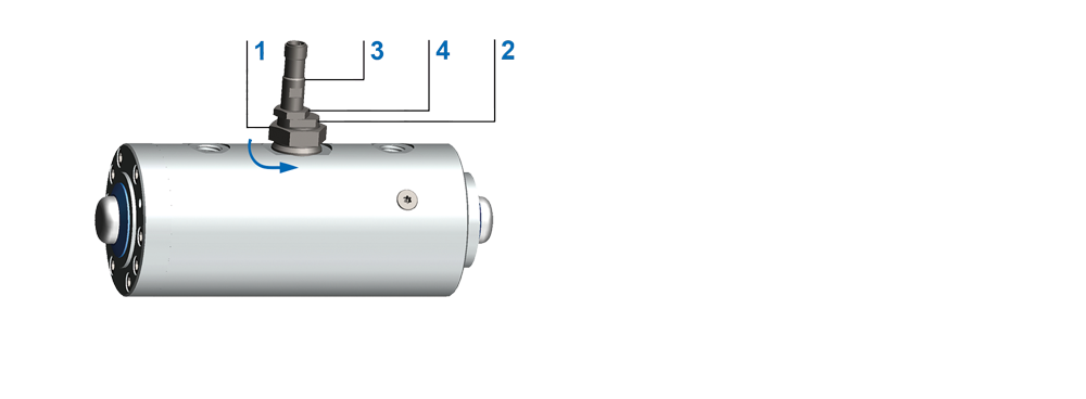
Set the proximity switch to released
|
|
- Loosen the lock nut (1).
- Turn the eccentric (2) until the proximity switch closes and the indicator light illuminates.
- Tighten lock nut (1) with max. 70 Nm.
- Ratio-Clamp® depressurize (pressure < releasing pressure).
Proximity switch opens. Indicator turns off.
If the proximity switch sends no signal or no signal in the desired position:
- Ensure that an operating voltage of 10 VDC to 30 VDC is present at the proximity switch.
- Pressurize the clamping unit Ratio-Clamp® with the minimum releasing pressure.
- Ensure that the clamping unit Ratio-Clamp® is released.
If the clamping unit Ratio-Clamp® is released:
- Loosen the lock nut (1).
- Turn the eccentric (2) until the proximity switch closes or the indicator lights up.
- Tighten lock nut (1) with max. 70 Nm.
- Relieve pressure from the clamping unit Ratio-Clamp®.
- Ensure that the indicator light goes out or the switch opens.
If the proximity switch does not switch in either the released or locked state:
- Remove plug.
- Loosen lock nut on proximity switch (4).
- Unscrew the proximity switch.
- Connect the plug.
- Check if operating voltage of 10 VDC to 30 VDC is present at the proximity switch.
If operating voltage is present:
- Guide the proximity switch with its end face towards the steel component.
If the proximity switch activates approx. 0.5 mm to 0.8 mm before touching the steel part: The proximity switch is functioning correctly.
- Reinstall the proximity switch.
- Tighten the lock nut of the proximity switch (4) with max. 15 Nm.
If the proximity switch does not activate approx. 0.5 mm to 0.8 mm before touching the steel part: The proximity switch is defective.
- Replace proximity switch.